E
Pa
g.
6
- M
anu
ale
FA
01
15
8 -
IT
- 0
2
/2
0
2
3 - © C
A
M
E S
.p
.A
. - T
radu
zio
ne d
elle ist
ru
zio
ni o
riginali
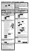
Fissaggio delle staffe
Determinare il punto di fissaggio della staffa cancello e quella della staffa pilastro, rispettando le quote riportate nella tabella.
Maggiore è l'angolo di apertura dell'anta, maggiore è la velocità di apertura e minore la spinta del motoriduttore.
Minore è l'angolo di apertura dell'anta, minore è la velocità di apertura e maggiore è la spinta del motoriduttore.
Dimensioni applicazione (mm)
KR300 - KR302 - KR310 - KR312
Apertura anta (°)
A
B
C MAX
E
90°
130
130
60
910
120°
130
110
50
910
KR510 - KR512
Apertura anta (°)
A
B
C MAX
E
90°
200
200
120
1310
130°
200
140
70
1310
INSTALLAZIONE
⚠
Le seguenti illustrazioni sono solo esempi, in quanto lo spazio per il fissaggio del motoriduttore e degli accessori varia a seconda degli ingombri.
Spetta all’installatore scegliere la soluzione più adatta.
I disegni si riferiscono al motoriduttore installato a sinistra. L’installazione del motoriduttore a destra è
simmetrica.
Posa dei tubi corrugati
Predisporre delle scatole di derivazione e dei tubi corrugati necessari per i
collegamenti provenienti dal pozzetto di derivazione.
Il numero di tubi dipende dal tipo di impianto e dagli accessori
previsti.
Staff a cancello
Staff a pilastro
Pa
g.
6
- M
anu
ale
FA
01
15
8-
IT
- 0
2
/2
0
2
3 - © C
A
M
E S
.p
.A
. -
Ist
ru
zi
on
i o
riginali