Page 22 of 26
CX-33PS Advanced L
ogic Cont
rol Relay & P
ower Supply C
abinet
IN
ST
ALLA
TION
IN
STR
UC
TION
S
FILENAME:
CX
-33PS Diagram 12.ai
D
R
AWING
No:
DRG-CX-33-PS-12
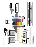
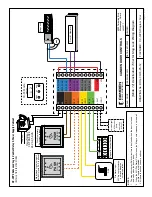
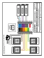
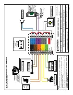
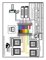
(Mode 12) Deactivation Timer for Mag Lock
W
iring Diagram
S
C
A
LE
:
N
O
N
E
D
R
AWN
BY:
JML
R
E
VI
SE
D:
DATE: 04/17/2020
55
02
T
im
be
rle
a
B
lv
d.
M
iss
is
sa
ug
a, O
ntar
io
L4
W
2
T7
CAM
DEN
D
O
O
R
CO
NT
RO
LS
NOTES:
1.
The magnetic contact Switch circuit must be closed when the door is closed,
and open when the door opens.
2.
When the N/O Fire
Alarm Circuit closes, the Mag Lock is released, and the wall
switch inputs are disabled.
3.
All items in dashed lines are optional.
Magnetic Contact Switch
Fire
Alarm Input.
N/C dry contact unlocks
door and disables normal operation
MOV
N.C.
AC
AC
DRY 1
IN
PUT
DRY 2
IN
PUT
DRY 3
IN
PUT
DRY 4
IN
PUT
+
W
ET
-
IN
PU
T
RELAY 1 COM
RELAY 1 N
O
RELAY 1 N
C
RELAY 2 COM
RELAY 2 N
O
RELAY 2 N
C
RELAY 3 COM
RELAY 3 N
O
RELAY 3 N
C
*
+
VD
C
-
VD
C
DISPL
AY
MENU
UP
DOWN
0.
1
.
2
CX
-33
M
ode
12
0
VA
C
Tr
an
sf
or
m
er
CX-
TR
X-5024
24
VA
C,
50 VA
PUSH
TO OPEN
PUSH
TO OPEN
Mag Lock
FIRE
Wire Momentary
Switch(es) to Input 1
Maintained Signal on Input 2 holds Outputs 2 & 3 (optional)
Door #1 Operator
Po
w
er
ed Signal
ie. RF Receiver
(same
ope
ration
as Dry 1)


