Page 11 of 26
CX-33PS Advanced L
ogic Cont
rol Relay & P
ower Supply C
abinet
IN
ST
ALLA
TION
IN
STR
UC
TION
S
FILENAME:
CX
-33PS Diagram 3.ai
D
R
AWING
No:
DRG-CX-33-PS-03
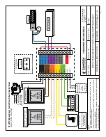
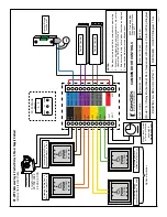
(Mode 3) 2 Door
Ratchet
Airlock
W
iring Diagram
S
C
A
LE
:
N
O
N
E
D
R
AWN
BY:
JML
R
E
VI
SE
D:
DATE: 04/17/2020
55
02
T
im
be
rle
a
B
lv
d.
M
iss
is
sa
ug
a, O
ntar
io
L4
W
2
T7
CAM
DEN
D
O
O
R
CO
NT
RO
LS
NOTE:
1.
Door Contact circuit must be closed when door is closed,
and open when door opens.
2
. If electric lock is not used, set H1 and D1 timers to 0.D2
is not used in this mode.
3. Walk-away feature is used with locks only (not operators). Otherwise, set H2 & H3 Timers to 0.
Activating Switch(es)
Door 1
Optional Electric
Lock Door #1
MOV
N.C.
N.C.
Magnetic Contact
Switch Door 1
Magnetic Contact
Switch Door 2
AC
AC
DRY 1
INP
UT
DRY 2
INP
UT
DRY 3
INP
UT
DRY 4
INP
UT
+
W
ET
-
IN
PU
T
RELA
Y 1 COM
RELA
Y 1 N
O
RELA
Y 1 N
C
RELA
Y 2 COM
RELA
Y 2 N
O
RELA
Y 2 N
C
RELA
Y 3 COM
RELA
Y 3 N
O
RELA
Y 3 N
C
*
+
VD
C
-
VD
C
DISPL
AY
MENU
UP
DOWN
0.0.
3
CX
-33
M
ode
12
0
VA
C
Tr
an
sf
or
m
er
CX-
TR
X-5024
24
VA
C,
50 VA
PUSH
TO OPEN
PUSH
TO OPEN
Activating Switch(es)
Door 2
Door #1 Operator
Door #2 Operator


