Page 7 of 26
CX-33PS Advanced Logic Control Relay & Power Supply Cabinet
INSTALLATION INSTRUCTIONS
Section 3 N
Special Purpose Sequencer (Mode 13)
In this mode, Input 1 sequences Relays 1 & 2, Input 2
sequences Relays 2 & 3. Input 3 sequences Relays 1 - 2 - 3,
and Input 4 sequences Relays 1 - 3 - 2.
Refer to Diagram 13 (Page 24) for connections. Once
input and output connections are made, program the unit
according to the General Programming Instructions on
page 1, and walktest the installation. Perform any timing
adjustments.
In addition, you can add a “Delay-on-activate” (or nuisance
delay) to this mode by setting time via Step 8 of the Program
Mode. If this feature is used, any input will have to be held for
at least the time indicated on the display before the CX-33 will
activate. If this feature is not wanted, set the time to zero (0.0)
Once the desired operation is achieved, proceed to Section 4,
(Page 9) for System Inspection Instructions.
Section 3 P
Delayed Relay Activation (Mode 14)
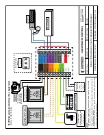
Refer to Diagram 14 (Page 25) for connections. In this unique
mode, a Switch connected to Input 1 will cause Relay 1 to fire
immediately, but not allow Relays 2 & 3 to fire until a pre-set
elapsed time has expired. The user must push and hold the
switch for this length of time. A Fire alarm input is provided –
DRY 2 or WET 1. A Bypass or Shunt Keyswitch is connected to
DRY 3, and a N/C door position switch is connected to DRY 4.
Output 1 is for a local siren, Output 2 is for the electric lock,
and Output 3 is for status monitoring.
Once connections are made, power up and adjust H1 time for
the length of time switch 1 must be pressed. H2 time is the
minimum ON time for Relay 2 (lock).
It is NOT recommended to add the “Delay-on-activate” (or
nuisance delay) feature in this mode.
Once the desired operation is achieved, proceed to Section 4,
(Page 9) for System Inspection Instructions.
Note: Not for use as UL compliant delayed egress.
Section 3 Q
Lock Down Mode (Mode 7)
In this mode, during normal operation the all-active switches
(both connected to Input 1) trigger the auto door operator.
When desired, a “Lock-Down” switch located remotely
(in a school office for instance) will activate the door lock,
and disable the door switch input. A separate output can
drive a status LED / light. When the “Reset” button (connected
to Input 4) is momentarily depressed the door unlocks, and
the system resets.
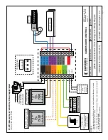
Refer to Diagram 7a (Page 26) for connections. The allactive
switches and Lock-down Switch are all normally open
switches. The RESET switch is normally closed. Connect as
shown. A fail-safe electric strike, or mag lock should be used.
Input 2 allows for an optional secure entry keypad (or similar),
or connection to a fire alarm.
Once connections are made, power up and program the unit
according to the General Programming Instructions on Page 1,
and walk-test the installation. Adjust H1 time for the lock time,
D1 for the time between the lock and operator, and H2 for
the time delay for the auto door operator. D2 and H3 are not
used in this mode.
It is NOT recommended to add the “Delay-on-activate” (or
nuisance delay) feature in this mode.
Once the desired operation is achieved, proceed to Section 4,
(Page 9) for System Inspection Instructions.
Section 3 R
Bi-Directional Door Sequencer with
Access Control Input (Mode 15)
This mode sequences all 3 relays in both directions, also
known as bi-directional door sequencing. Refer to Diagrams
15a & 15b on pages 27 and 28.
Access control systems can be connected to the WET input to
unlock the door before sequencing the operators. The door
remains unlocked while there is a maintained signal on the
WET input.
DRY1 input is only active while there is signal on the WET input.
DRY 1 input sequences Relay 1 to Relay 2 to Relay 3.
DRY 2 input sequences Relay 3 to Relay 1 to Relay 2.
DRY 2 input will always unlock the door before sequencing
Input 3 only sequences Relay 1 to Relay 2, and Input 4 only
activates Relay 3.
If a relay (Relay 1 for example) operation is not desired it
can be turned off by setting the time delays to zero (in this
example H1 & D1).
Once input and output connections are made, program the
unit according to the General Programming Instructions on
page 1 and walk-test the installation. Timing adjustments may
need to be made.
In addition, you can add a “Delay-on-activate” (or nuisance
delay) to this mode by setting time via Step 8 of the Program
Mode. If this feature is used, any input will have to be held for
at least the time indicated on the display before the CX-33 will
activate. If this feature is not wanted, set the time to zero (0.0)
Once the desired operation is achieved, proceed to Section 4,
(Page 9) for System Inspection Instructions.


