®
SECTION 2: SETUP
making
since 1986
water work
SECTION 2: SETUP
The Setup section of the controller is used to access
programming the following:
•
Communication
addresses
•
Controller’s Part & Serial number
information
•
Date & Time
•
Stations in Use
•
12 month scheduling
•
Access Codes
2A. COMMUNICATIONS
Skip communication setup section if controller(s)
has no communications option installed.
The Communications screen can be used to set the
communications address in the controller. This
address is used for communicating back to a central
computer, and is also used to differentiate one
controller from another in a communications chain.
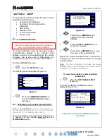
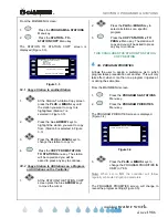
From the MAIN MENU screen:
1.
Press the
SETUP
Menu key.
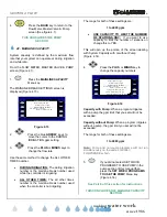
The SETUP screen is displayed (Figure 2.1).
ET2000e-48-M-SR (605.b)
Communication 12 Month Mode
Part & Serial Numbers
Date & Time
Stations In Use Access Control
Figure 2.1
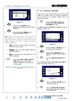
2.
Press the
COMMUNICATION
Menu
key, the COMMUNICATION screen
will appear.
2A.1 Controller(s) with central communication:
Note:
If
FLOWSENSE
®
option is installed (this can
be verified by looking for a (-FL) in the part number.
(See Section 11 for detailed instructions).
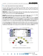
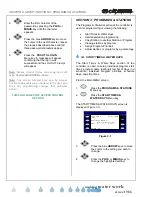
The communication screen should look like the one
in Figure 2.2 if your controller
does not
have the
FLOWSENSE
®
option.
NO
Communications Address: ! ! A
ET2000e-40-M-SR-FL (605.b)
does this controller coordinate with
Using FLOWSENSE Technology
other controllers to share MASTER
VALVES, FLOW METERS, or PUMPS?
Controller Info
Figure 2.2
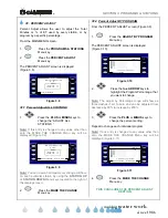
1.
Press the blue
ARROW
keys to
highlight the Communications
Address.
2.
Press the
PLUS
or
MINUS
keys to
set the first character.
3.
Press the blue
ARROW
keys to move
the cursor to the next character.
Repeat the process described above until all three
characters are set (The character furthest to the right
must be a letter).
Note:
. No two controllers can have the same
address when communicating to the same central
computer via a single central device.
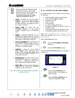
To view the controller’s communications
information:
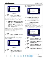
4.
Press the
CONTROLLER INFO
Menu key.
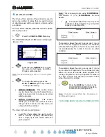
The PART & SERIAL NUMBERS screen is
displayed (Figure 2.3).
Copyright Calsense Inc. 1987-2006
A: L H L L L L
B: L L L L L L ( -SR )
C: L L L L L L
D: L L L L L L
Serial Num: 00000 CC4 Ver: 4.2.0.15
( the normally expected signal levels )
RTS CTS DTR DSR CD RI
PART & SERIAL NUMBERS
ET2000e-48-M-SR C=144000 D=9600
602.a s=1 c=6 A=14400 B=19200
Figure 2.3
THIS CONCLUDES THE COMMUNICATIONS
SECTION


