background image

11

Flow Meter Setup

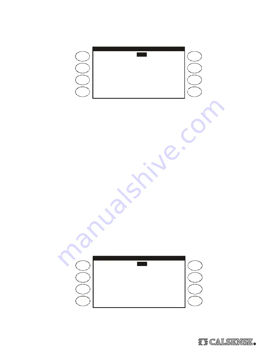
From the Flow Meter, Master Valve & Pump Setup screen, Press the 

FLOW METER

 Menu Key, the Flow Meter screen will appear

(it will appear as shown below only after the Flow Meter In Use setting is set to YES). Press the 

ARROW

 Key to move the cursor

to the desired setting, the three settings are described below.

FLOW  METER

Flow  Meter  is  in  use ?   

Choose  the  Flow  Meter  from  a  list  OR
set  your  own  Parameters ?

CHOOSE  FROM  LIST

Meter 1

CHOICE:

NOT USED

Is  this  a  MASTER  CONTROLLER ?   NO

YES

1. The first setting is the type of flow meter installed on the system. If the flow meter is a standard Calsense Flow Meter, leave the
setting at CHOOSE FROM LIST (the default setting). If the flow meter is a Calsense FMBX, change the setting to ENTER OWN
PARAMETERS (described later on this page).

2. The next setting is the model of flow meter installed (the default setting is NOT USED). The list of choices are:

FM-1

1” plastic flow meter

FM-1B

1” brass flow meter

FM-1.25B

1 1/4” brass flow meter

FM-1.5

1 1/2” plastic flow meter

FM-2

2” plastic or brass flow meter

FM-3

3” plastic flow meter

NOTE : Most Calsense Controllers are connected to only one flow meter, which is why the choice of flow meter model heading
in the example screens show only Meter 1. If the controller has the -F option installed (use of multiple flow meters), there will be
three headings, Meter 1, Meter 2 and Meter 3, and a choice of model for each flow meter installed.

3. The MASTER CONTROLLER setting will appear with NO selected (as shown above). In most cases this setting will not change.
If a system has multiple controllers on a single mainline, and more than one controller has to irrigate at the same time, one controller
is designated as the master controller (and is connected to a Calsense flow meter). All other controllers have flow monitoring
disabled. The job of the master controller is to continuously monitor for mainline breaks, no other flow monitoring features will be
enabled for the master controller.

If the flow meter installed on the system is a Calsense FMBX change the Choose Flow Meter setting to ENTER OWN
PARAMETERS (the screen will appear as shown below).

FLOW  METER

Flow  Meter  is  in  use ?   

Choose  the  Flow  Meter  from  a  list  OR
set  your  own  Parameters ?

ENTER  OWN  PARAMETERS

Meter 1

K:

10.000

OFFSET:

0.200

Is  this  a  MASTER  CONTROLLER ?   NO

YES

The two settings that must be set are the K value and the OFFSET value. Follow the instructions that are shipped with the Calsense
FMBX Flow Meter, or call Calsense at 800-572-8608 for assistance.

Содержание ET2000

Страница 1: ...rlsbad CA 92011 1 800 572 8608 FAX 760 438 2619 www calsense com ET2000 PROGRAMMING GUIDE CONTROLLER STATUS adjust stations No Stations are Watering NEXT SCHEDULED IRRIGATION IS AT 12 00 AM on Saturday Aug 17 2002 Aug 16 2002 Sat 10 45 03 AM Stock No 4039 Rev 09 02 ...

Страница 2: ... Copy a Station to Another Station 10 Copy a Station to All Stations on a Program or All Stations on the Controller 10 8 Flow Meter Master Valve Pump Setup 10 Estimated Water Use 10 Flow Meter Setup 11 Flow Meter Settings 12 Master Valve 14 Pump Output 14 9 Manual Key 15 Manual Water 15 Test 15 Master Valve 16 Manual Special Sequence 16 Scheduled Manual Special Sequence 17 10 No Water Key 17 Turn ...

Страница 3: ... Station Order 21 Diagnostics 21 Log Lines 22 ET Rain Tables 22 16 Controller Status 23 Status Screen 23 Station Alerts 23 17 Weather Setup 23 Wind Gage Setup 24 Rain Switch Setup 24 Moisture Sensor Setup 25 18 Lights 26 Programming a Lights Schedule 26 Testing a Lights Circuit 26 19 Radio Remote 26 ...

Страница 4: ...xt between English and Spanish BACK The BACK key will go back to the previous screen MAIN MENU The MAIN MENU key is used to access the different pro gram features of the controller 10 1 7 9 8 5 6 4 3 MENU KEYS MENU keys select the different features or commands in the different screens and are adjacent to the left and right side of the controller s display screen The text in the screen will point ...

Страница 5: ...get Moisture ET County City if in Daily ET mode Limit Learned Delay Time Alert Action Mainline Break Use of Rain by Program Moisture Sensing Setup Crop Coefficents if in Daily ET mode Sensor Assignment if in Moisture Sensing mode Adjust Learned Numbers if in Learned mode Adjust Limit Numbers if in Limit mode Start Times Water Days Programs Stations Station to Station Copy Stations Finish Times Sta...

Страница 6: ...er controller Master Valve Select type of master valve Pump Output Select pump output type Select use of pump by program Limit Learned Select to use limit mode or learned mode Set all learned flow rates if in learned mode Set all high low limits if in limit mode Adjust learned flow rates if in learned mode Adjust high low limits if in limit mode Delay Time Set delay time Set trip Alert Actions Set...

Страница 7: ...pressing the MAIN MENU Key The descriptions on the screen with the arrows are pointing to the Menu Keys which are to be pressed to access the various parts of the controller s program see ET2000 Screen Map on page 5 Most programming functions will begin from the Main Menu As you navigate through the various screens you can always return to a previous screen by pressing the BACK key The last four k...

Страница 8: ...etting is optional Days in Schedule The ET2000 can be set with a 7 Day Schedule shown in the example above 14 Day Schedule 21 Day Schedule or 28 Day Schedule Water Days The days of the week in the schedule to irrigate on represents a water day represents an off day Hold Over Time A time at which irrigation is forced to end even if the scheduled irrigation cycle is not finished This setting is to b...

Страница 9: ...il the total irrigation applied is 15 minutes the Total Mins setting this feature is called Cycle and Soak Each station s Cycle and Soak settings can be set independent of any other station s settings The following shows some examples of Cycle and Soak settings S TATION UP STATION PROGRAMMING Station 1 PROG A Total Mins Mins per Cycle 5 Soak In Time 60 No Water Day 0 Test 15 0 Station Up Key Stati...

Страница 10: ...creen Press the PLUS or MINUS Key until the station is selected station 2 was selected in the example above Press the COPY FROM STATION TO STATION Menu Key the station will be copied and you will be returned to the Programs Stations screen If you wish to copy the current station to another station Press the STATION TO STATION COPY Menu Key to return to the Station To Station Copy screen and repeat...

Страница 11: ...s why the choice of flow meter model heading in the example screens show only Meter 1 If the controller has the F option installed use of multiple flow meters there will be three headings Meter 1 Meter 2 and Meter 3 and a choice of model for each flow meter installed 3 The MASTER CONTROLLER setting will appear with NO selected as shown above In most cases this setting will not change If a system h...

Страница 12: ...ion approximatley 6 to 10 scheduled irrigation cycles are required to learn a station s flow rate The controller will then use this learned flow rate to alert the user when HIGH FLOWS and NO FLOWS occur Press the ARROW Key to move the cursor to the SET ALL LEARNED VALUES Menu Key use the PLUS or MINUS Key to set the desired gpm then Press SET ALL LEARNED VALUES the Menu Key to set the value This s...

Страница 13: ...ROG C Alert No Action Alert No Action PROG D Alert No Action Alert No Action PROG E Alert No Action Alert No Action DRIP 1 Alert No Action Alert No Action DRIP 2 Alert No Action Alert No Action MAINLINE BREAK MAX FLOW NUMBERS Mainline Break Numbers DURING IRRIGATION is gpm AT ALL OTHER TIMES is 700 gpm System Max Flow Capability is 999 gpm 700 The Alert Actions setting defaults with Alert No Actio...

Страница 14: ...UT Menu Key the Pump Output Options screen will appear shown below The Pump Output Used will be highlighted and the default setting will be set for NORMAL PUMP OUTPUT to change the setting Press the PLUS or MINUS Key There are three settings NORMAL PUMP OUTPUT if a pump is installed or if a pump is not installed and the output is not used for a special purpose STEADY ALERT LIGHT or BLINKING ALERT ...

Страница 15: ... Press the PLUS or MINUS to select the desired Program or ALL stations PROG A has been selected in the example above then Press the MANUAL WATER xxxx STATIONS Menu Key to start manually watering the selected program or all stations on the controller To end the manual cycle before all of the stations have run Press the STOP Key The last setting at the Manual Irrigation screen is the Cycle and Soak ...

Страница 16: ... PLUS or MINUS Key to select the OPEN or CLOSE setting Press an ARROW Key to move the cursor to the HOURS setting Press the PLUS or MINUS Key to set the desired number of hours of override Press the xxxx MASTER VALVE FOR x Menu Key to start the master valve override To end the override before the set end time Press the STOP Key Note Scheduled irrigation will not occur while the master valve overri...

Страница 17: ...manual special sequence is set to start it will be temporarily halted until the manual special sequence is finished then resume where it left off TURN CONTROLLER OFF NO WATER Turn Controller OFF Apply No Water Day s to PROG A 3 No Water Days Summary no water by station Turn a Controller Off Press the TURN CONTROLLER OFF Menu Key The controller will be turned off and will immediately return to the ...

Страница 18: ...cursor is highlighting the Total Mins setting and you Press the HELP Key you will access an explanation of the Total Mins setting After viewing a Help screen Press the BACK Key to return to the screen you were at when you Pressed the Help Key 12 English Spanish Key Press the ENGLISH ESPANOL Key to toggle between displaying text in English or in Spanish When in Spanish mode all Help screens will al...

Страница 19: ... controller cannot be programmed until the proper password has been entered at the Log In screen Enter Your Login 0 0 0 LOG IN LOG IN COMMUNICATIONS COMMUNICATION ADDRESS 406 p norm A 9600 B 9600 2000 BOARD ET2000 32 LR G RR Copyright Calsense Inc 1987 2001 All Rights Reserved Enter the first character of the password by Pressing the PLUS or MINUS Key until the character appears Press the ARROW Ke...

Страница 20: ...w is shown in the upper left corner of the screen gallons in the example above The upper part of the screen shows controller usage totals the lower part of the screen shows individual station usage totals Press the STATION UP or STATION DOWN Menu Keys to view the desired station station 8 is shown in the example above The totals are listed in two columns The Month column is the total water usage s...

Страница 21: ... inactive and stations 7 and 8 are not being used they have been turned off at the Station In Use screen Station 2 is irrigating and has 8 5 minutes left to irrigate Station 3 has completed an irrigation cycle and is in a soak in cycle it also has 8 3 minutes of hold over time Stations 1 4 and 5 are waiting to start their first irrigation cycle You can use the Irrigation Detail screen to view the ...

Страница 22: ...Low Current H High Flow R Irrigation Halted Due To Rain W No Water Moisture Sensor Alerts only if moisture sensing is enabled M Moisture Sensor Caused Cycle Skip O Reading Not Put In Line Yet R Reading Out Of Range X Moisture Sensor Max Water Days Set F No Filtered Reading S Signal Never Went Away Reading Never Taken ET Rain Tables ET AND RAIN TABLES ET Table from 10 29 2001 back Mon Sun Sat Fri T...

Страница 23: ...ption is installed on the controller which includes the Calsense ET Gage Rain Bucket and Wind Gage also a rain switch if one is installed You can also access the setup of daily ET water budgets and moisture sensors The following sections describe Rain Bucket settings on a controller without the RB interface Wind Gage setup Rain Switch setup and Moisture Sensor Setup setup of the ET Gage and the Ra...

Страница 24: ... stay in this mode until the wind decreases to 15 MPH or less and stays at 15 MPH or less for 20 minutes when this criteria is met irrigation will resume where it left off Rain Switch Setup RAIN SWITCH SETUP Is the controller connected to a Rain Switch Device Irrigation will be STOPPED when the rain switch detects rain A Rain Switch is a device like a MINI CLIK or RAIN GUARD There is special way t...

Страница 25: ...r the same as the it s station number these stations are know as a Master In the example above stations 1 7 10 13 19 and 24 are Master stations All other valves will use the readings from one of the Master stations This is done by assigning each of these stations to a Master station In the example above stations 2 3 and 4 have been assigned to station 1 stations 5 6 and 8 have been assigned to sta...

Страница 26: ...f the 14 day schedule set the ON OFF TIMES as described above repeat this process until all 14 days have been programmed This schedule will continually repeat itself every 14 days Testing a Lights Circuit Station Up Key Station Down Key S TATION U P Test LIGHTS SCHEDULING MANUAL OPERATION L1 Schedule for ON TIMES 10 00PM OFF OFF TIMES 11 30PM OFF Sep 17 2002 Tue Status OFF To turn on a lights circ...

Отзывы: