2
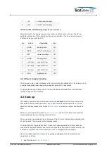
RS232 0 RX
IN
3
GND
4
RS232 1 TX
RS232 for remote control
OUT
5
RS232 1 RX
IN
6
GND
7
RS422 TX+
RS422 for remote control
OUT+
8
RS422 TX-
OUT-
9
RS422 RX+
IN+
10
RS422 RX-
IN-
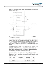
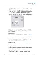
The ACU is factory preset to use the RS422 interface in 4-wire configuration. To change the
interface configuration, set the jumpers on the ACU main board above CON8 according to the
illustration below
JP1 selects between the RS232 and the RS422 interface driver. Put the jumper to position 1-
2 (left) to select the RS232 interface.
JP2 switches between the RS422 4-wire mode and RS485 2-wire mode. To select RS485 2-
wire mode put the jumper to position 1-2 (left). Use the TX data lines (CON8 Pins 7, 8) in this
mode.
JP4 and JP5 activate 100 Ohms termination resistors between the RS422 data lines. The
lines are terminated if the jumper is set.
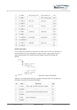
CON9 Power Supply
At CON9 the power supply for the ACU itself (pins 1, 2) and for the external switches must be
connected. Also see chapter
4.2.3 Power Supply Cabling
for the concept of separate intern /
extern power supplies the ACU uses.
pin
signal
description
type
(C) 2022, SatService GmbH
www.satnms.com
ACU-ODM-UM-2209 Page 12/73


