The outside of the equipment may be cleaned using a lightly dampened cloth. Do not use
any cleaning liquids containing alcohol, methylated spirit or ammonia etc.
Follow standard Electrostatic Discharge (ESD) procedures when handling the Unit.
Apply the appropriate voltage according to the attached schematic.
In case of switching off all the circuit breakers is still voltage available at the mains terminals!
Only use shielded cable to connect the AZ- and EL-Motor. The other components in the
cabinet might be jammed through the harmonic waves the frequency inverters inject into the
motor wires.
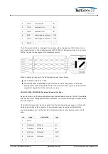
Use only double shielded twisted pair cables (e.g. CAT7 Ethernet cable) to connect the
resolvers to the sat-nms ACU
Only ACU-ODU : If the Unit is equipped with an optional air ventilation, avoid direct contact
with jets of water, normal rain is no problem.
The sat-nms Antenna Control Unit (Outdoor Module) is an antenna controller / positioner with
optional satellite tracking support. It may be operated as a stand alone unit or in conjunction of
the sat-nms ACU-IDU, a PC based indoor unit which offers extended tracking capabilities and a
full featured visualization interface. The ACU-ODM is designed as a closed, compact module,
prepared for mounting on a 35mm DIN rail.
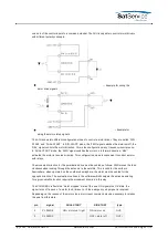
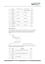
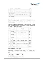
Below the top viw and connector layout of the ACU outdoor module is shown. Except the network
connector which is a standard 10-Base-T Ethernet socket, all connectors are Phoenix Contact
Combicon plugs / clamps.
Inside, the ACU consists of a main board and two or three interface boards with the circuitry for
the position sensors. These boards are different for each type of position sensor. Actually
interfaces for three types of position encoders are available with the sat-nms ACU:
resolvers
SSI digital position encoders
analog voltage based sensors
You have to decide at date of order which interfaces you need.
The sat-nms ACU-ODM is powered by 2 different power supplies:
24V ACU: for ACU internal use, especially for the core processor
24V EXT: for external signals, e.g. limit switches, drive signals etc. By this a maximal reliability
of the sat-nms ACU-ODM is ensured.
The following chapter describes how to install the ACU-ODM mechanically and electrically.
Additional a detailed start-up procedure is given in this chapter.
(C) 2022, SatService GmbH
www.satnms.com
ACU-ODM-UM-2209 Page 7/73


