


1
+24V ACU
power supply for the ACU and the
2
GND ACU
positional encoders
3
+24V EXT
power supply for motor drivers and
4
GND EXT
external switches
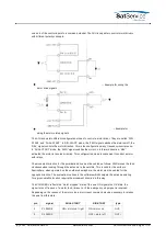
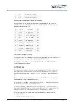
CON10 Azimuth Motor Driver
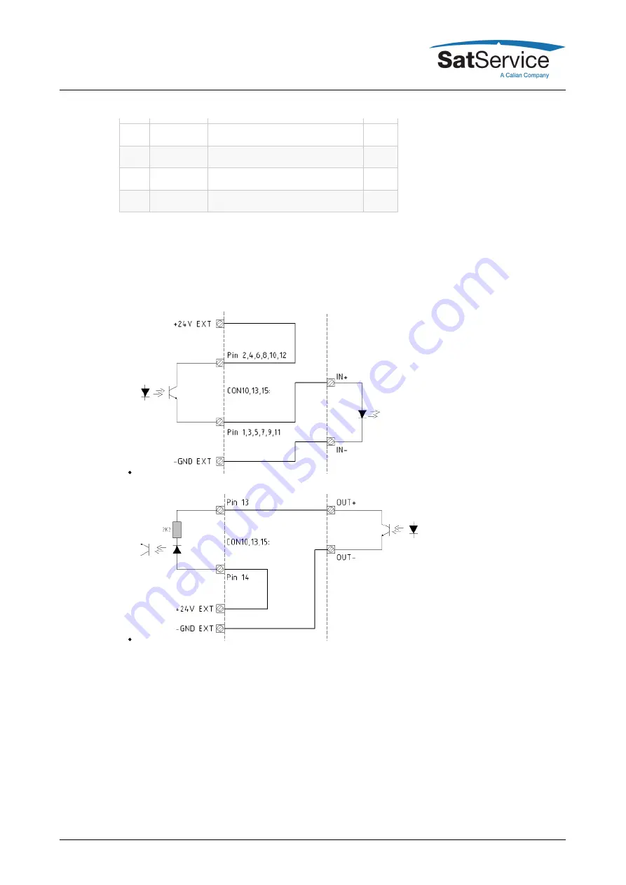
All signals for motor control are provided as free floating opto coupler inputs / outputs. This gives
a maximum of flexibility to adapt the cabling to the motor driver units. They probably will combine
one end of the control inputs to a common potential. The ACU is capable to control motor drivers
with different polarity concepts.
--- Example for wiring the
motor drive signals
--- Example for
wiring the motor status signals
The ACU knows two different configuration modes to control a motor driver. They are called 'DIR-
START' and 'DUAL-START'. In 'DIR-START' mode, the 'FWD' signal switches the motor on/off, the
'REV' signal controls the motor direction. This is the configuration many frequency inverters use.
In 'DUAL-START' mode, the 'FWD' signal switches the motor on in forward direction, 'REV'
activates the motor in reverse direction. This configuration mode is convenient to control a motor
with relays.
The movement direction for the azimuth drive must be cabled as follows: FWD moves the antenna
to the west (to the right on the northern hemisphere). The evaluation routines in the software
which compute the antenna pointing for a given satellite location require the movement direction
in this way.
(C) 2022, SatService GmbH
www.satnms.com
ACU-ODM-UM-2209 Page 13/73


