background image

SATK40 & Procyl

®

8

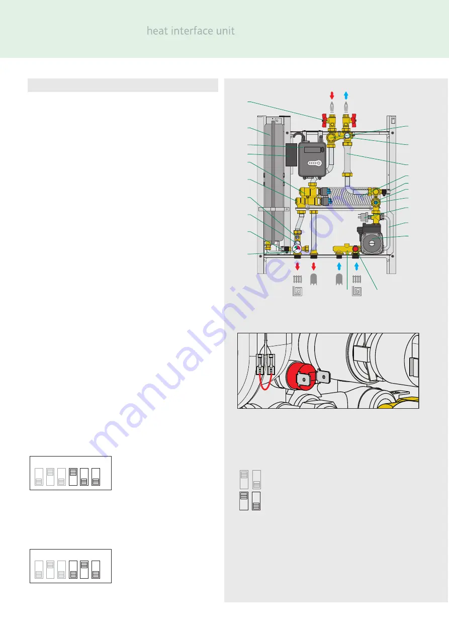
Components - SATK40103

Item Component

1

Frame

2

Expansion vessel

3

Electronic control unit

4

Primary modulating control valve

5

Three port diverting valve

6

Plate heat exchanger (DHW + space heating)

7

Safety relief valve - 3 bar

9

Drain cock

12

Heat meter spool piece - replaced by heat meter when fitted

14

Heating flow temperature sensor

15

Pump

16

Pump safety bypass

18

DP switch 

19

Strainer (heating circuit)

22

Primary filter and heat meter probe pocket

23

Heating return temperature sensor

24

Primary isolation valve

25

Probe

26

Pressure gauge

27

Electric connection box

26

Filling loop double check valve

*

27

Filling loop

*

28

Filling loop isolation valve

*

29

Room controller

*

(not supplied)

*

Not shown on Components illustration

Functional characteristics

Heating range: 

LOW temperature setting 25 to 45˚C.

MEDIUM/HIGH temperature setting 50 to 75˚C

Optional functions

Heating cycle:

modulating temperature regulation with 
compensated set point floor slab heating 
function.

Factory settings

SATK 40103 HIUs are factory set to support 

MEDIUM

/

HIGH

temperature heating (50 to 75˚C) with the dip switches set as
shown.

To modify the factory settings and enable the HIU to support

LOW

temperature systems (25 to 45˚C) proceed as follows;

1

Switch off the electricity power supply to the HIU

2

Set the switches 2 and 3 with the ON-OFF setting

3 Remove the safety thermostat jumper cable and 

connect the cables to the thermostat. 

4

Switch on the electricity power supply to the HIU.

Factory settings

Factory set - DO NOT CHANGE

May be switched to activate optional functions
Switch 1:  

modulating temperature regulation


with compensated set point

Switch 2-3:  change setting

ON

1

2

3

5

6

4

1

0

2

3

4

ON DHW CH FAULT

RESET

1

2

1

20

11

5

28

14

15

2

24

19

4

2

3

16

17

23

22

8
2

12

18

21

ON

1

2

3

5

6

4

Содержание Altecnic SATK40103

Страница 1: ...SATK40 Procyl heat interface unit Installation Operation Maintenance Instructions...

Страница 2: ...tures higher than 50 C may cause severe burns When installing commissioning and maintaining the device take the necessary precautions so that these temperatures will not be hazardous for people Conten...

Страница 3: ...t off the electric supply before opening the HIU cover 1 During installation and maintenance operations always avoid direct contact with live or potentially hazardous parts 2 The device must not be ex...

Страница 4: ...he position of the water pipe connections Check the measurements again before installing pipework and electrical cables Hydraulic connections 1 connection to the pipework from the centralised boiler p...

Страница 5: ...ve earthing system constructed as speci ed in current safety regulations This is a compulsory safety requirement Connection to the main supply The device is supplied with an electric supply cable plug...

Страница 6: ...repeat the lling process if necessary Fitting the cover Place the casing over the frame inserting the upper tabs 1 into the corresponding slots 2 Place the lower part of the casing over the frame Tig...

Страница 7: ...circuit pressure switch fault Error code 4 The SATK40 HIU continuously monitors the pressure in the apartments secondary heating circuit If the pressure falls in this circuit the pressure switch is a...

Страница 8: ...power failure the thermal safety valve prevents hot water for heating purposes from entering the system After the user has reset the isolation imposed by the safety thermostat the shut off valve can...

Страница 9: ...e setting 25 to 45 C MEDIUM HIGH temperature setting 50 to 75 C Optional functions Heating cycle modulating temperature regulation with compensated set point floor slab heating function Factory settin...

Страница 10: ...is requested by the room thermostat the circulation pump is powered while the modulating valve is opened gradually until the set point temperature is reached At the end of the heating cycle the circu...

Страница 11: ...etter ef ciency and helps to save energy Before carrying out any maintenance repair or part replacement work proceed as follows Switch off the electric supply Remove the cover Close the shut off valve...

Страница 12: ...cting the connector see page 16 Unscrew the probe Fit the new probe Reconnect the connector respecting the only possible way it can be inserted Expansion vessel pre charge check For the system to work...

Страница 13: ...lay Fused Switch 21 22 6 7 10 11 1 2 3 4 2 5 Com N SL L N E HW On 1 2 3 8 4 CH On 8 9 9 2 10 11 1 2 3 L N E Wiring Centre 7 8 9 10 11 1 2 3 4 5 6 5 2 6 7 L N Br Bl Gr Or Not supplied wiring to be made...

Страница 14: ...i ed personnel to have it replaced electronic controller not working call quali ed personnel to have it replaced all LEDs are off electricity power supply switched off switch on electricity supply pro...

Страница 15: ...faulty call quali ed personnel to have it replaced presence of air in the system vent the system pump not working call quali ed personnel to have it replaced pump cable not connected restore connecti...

Страница 16: ...ecnic co uk IOM 033 23 10 15 E O E Notes In these Installation Operation and Maintenance Instructions we have endeavoured to make the information as accurate as possible We cannot accept any responsib...

Отзывы: