FAST-PS-M – User’s Manual
19
By using these two “sensing” pins it is possible to sense the output voltage
directly on the load, thus recovering possible voltage drops on the output cables up to
0.5V.
It is strongly suggested to use twisted cables when using the
remote sensing
feature in order to minimize possible noise pick-up.
The FAST-PS-M is shipped with a mating connector for the remote sensing that
short-circuits the +S and + pins and the –S and – pins respectively. This configuration
performs the remote sensing directly at the output connector of the power unit. Leaving
+S and –S pins disconnected will make the power supply sense the output voltage
directly at the output terminal connections. When using the remote sensing feature leave
pins #2 (+) and #3 (
–
) disconnected.
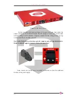
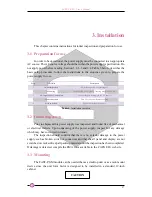
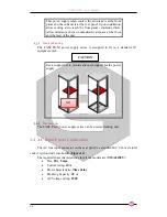
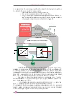
In order to perform remote sensing at different points – e.g. the load terminals
– it would be necessary to connect Pin #1 and Pin #4 as in
Figure 7
:
Figure 7
: Example of Remote Sensing
2.2
Options
The FAST-PS-M can be configured with options that are factory-configured and
can be found on the rear panel in places of connectors A and B.
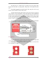
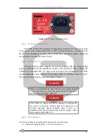
The standard version of the FAST-PS-M, on the rear panel, is as shown in the
following
Figure 8
and
Figure 9
.
FAST-PS
LOAD
+S
-S
+
-
Power Cables
Sensing Cables
OUTPUT
CONNECTOR


