FAST-PS-M – User’s Manual
30
•
Maximum wire length.
•
Insulation voltage
Wire cross section and length
Wire size should be selected to enable voltage drop per lead to be less than 1 V
at the maximum power supply current to prevent excessive output power consumption.
Suggested wire size are listed in the following table:
Wire Cross Section
Area [mm
2
]
Resistivity [Ω/km]
Maximum Cable length in meters to limit
voltage drop to be less than 2 V (1 V per
lead)
60 A
75 A
100 A
10
1,95
8.5
6.5
5
16
1,24
13.5
10.5
8
25
0,795
20.5
16.5
12.5
35
0,565
29.5
23.5
17.5
Table 6:
Wire selection
The cable has to be connected directly to the bass-bar using lug terminals M6
screws. If Table 6 values are used the maximum voltage to the load will be limited to:
FAST-PS-M nominal output voltage + Maximum compensation
Voltage if Remote sensing is used – Cable Drop Voltage
Maximum compensation Voltage for all models is 0.5 V
For instance, the FAST-PS-M 10006-600 that have a nominal output voltage of 6 V
connected to a load at 8 meter of distance using 2x16 mm
2
cable can drive at maximum
6+ 0.5 - 2 =
4.5 V
at 100 A on the load.
Remote Sensing
A short from
V
SENS
+
or
V
OUT
+
to
V
SENS
–
or
V
OUT
–
will
cause damage to the power supply. Reverse the sense wire
might cause damage to the power supply in local and remote
sensing. Do not connect
+S
to
–
or
–S
to
+.
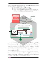
Use remote sense where the load regulation at the load end is critical. In remote
sense the power supply will compensate for voltage drop on load wires. Refer to the
power supply specification for maximum voltage drop on load wires. The voltage drop
CAUTION


