INSTALLING THE CONCENTRATOR MODULE
3-5
module connects to the transmit pair in the station. This provides
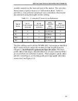
the necessary signal crossover or null modem effect. Table 3-1
provides a cross-reference of pinouts for connections that may be
encountered along the length of lobe cabling.
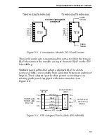
The lobe cabling used with the TRMIM-42A/44A requires shielded
RJ-45 connections to attain the maximum lobe lengths listed in
Chapter 2, Installation Requirements/Specifications. Shielded
patch cables that adapt a shielded RJ-45 to a Data Connector (MIC)
are available from Cabletron Systems. These adapter/patch cables
permit connecting to an existing patch panel equipped with data
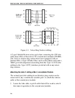
connectors (see Figure 3-3).
Table 3-1 Connector Pinout Cross-Reference
Signal
Name
RJ-11
6-pin modular
connector
RJ-45
8-pin modular
connector
Data
Connector
(MIC)
connector
DB-9
9-pin D-shell
genderless
TX+
5
6
O (Orange)
9
TX-
2
3
B (Black)
5
RX+
3
4
R (Red)
1
RX-
4
5
G (Green)
6

