B-6
cab - Produkttechnik GmbH
Circuit Diagram of Inputs and Outputs
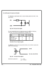
The inputs are optocouplers with a current limiting resistor of 2.4k
Ω
in the
input circuit.
[IN]
[IN]R
Fig. B-8 Circuit of the inputs
[IN]
Pin [IN]
Pin [IN]R
Print start
8
15
Label was taken
7
14
External error
6
13
Table B-4 Pairs of input signals
For each signal [IN] there is a separate reverse line [IN]R via the plug
connector. From that the following pairs of signals result :
All outputs are switched by relays which all have one common reverse line
(PIN 10 of the the plug).
[OUT]
Reverse line (Pin10)
Fig. B-9
Circuit of the outputs
Electrical requirements :
U
max
= 42 V
I
max
= 100 mA

