33
A 3
4.3
Wechsel des Druckkopfes
Der Drucker ist so konzipiert, dass ein
Druckkopfwechsel ohne jegliche Nach-
justage am Gerät durchgeführt werden
kann. Dies gilt sowohl für den Ersatz
verschlissener Druckköpfe als auch für
einen Wechsel zwischen Druckköpfen mit
203 dpi und 300 dpi Druckauflösung.
Druckkopf-Justageverlust!
Der Druckkopf ist auf einer Zwischen-
platte vormontiert und damit exakt ausge-
richtet. Lösen Sie daher auf keinen Fall
die Schrauben (4) mit denen der Druck-
kopf (1) an der Zwischenplatte (2) befe-
stigt ist. Die Grundjustage des Druck-
kopfes geht damit verloren!
Wechseln Sie den Druckkopf wie folgt:
1. Trennen Sie den Drucker vom Netzanschluss!
2. Entnehmen Sie das Material aus dem Drucker.
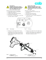
3. Schwenken Sie den Hebel (5, Bild 17) in die gezeigte
Stellung. In dieser Stellung ist die Druckkopfbaugruppe
entriegelt, liegt aber noch auf der Druckwalze auf.
4. Lösen Sie die Feststellschraube (6, Bild 17) für den
Druckkopf (1) mit dem Innensechskantschlüssel (2,5
mm) mit Griff (7, Bild 17).
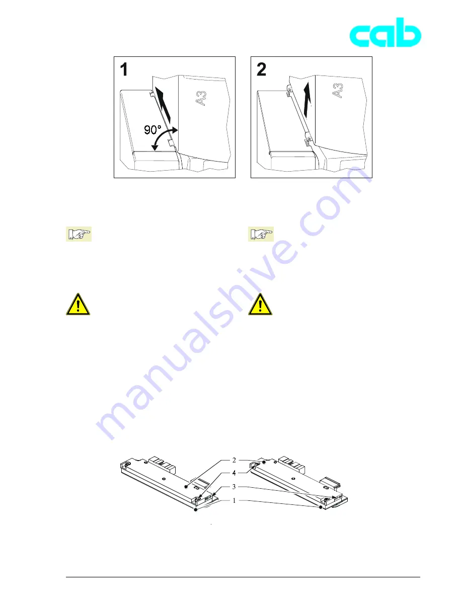
Bild 16
1 Druckkopf 203 und 300 dpi und
2 Zwischenplatte
3 Druckkopf-Kennzeichnung
4 Schrauben
Fig. 16
1 Printhead 203 and 300 dpi and
2 Headplate
3 Printhead identification
4 Screws
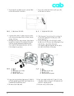
Bild 15
Deckel demontieren
Fig. 15
Removing the cover
4.3
Replacing the printhead
The printer is designed so that the
printhead can be replaced without making
any readjustments to the device. This
applies both when replacing worn out
printheads and switching between 203 dpi
and 300 dpi print resolution printheads.
Loss of printhead adjustment!
The printhead is pre-assembled to a head
plate, and thus exactly aligned. On no
account loosen the screws (4) that attach
the printhead (1) to the head plate (2) as
the basic adjustment of the printhead will
be lost.
Replace the printhead as follows:
1. Disconnect the printer from the mains connection.
2. Remove the media from the printer.
3. Swing the lever (5, figure 17) into the position shown.
In this position, the printhead assembly is unlocked but
still lying on the print roller.
4. Loosen the printhead (1) locking screw (6, figure 17)
with the 2.5 mm Allen key with handle (7, figure 17).
Содержание A3
Страница 1: ...Transferdrucker Transfer Printer Serviceanleitung Service Manual Ausgabe Edition 3 02 ...
Страница 23: ...21 A 3 Bild 6 Geräteliste Fig 6 Device list ...
Страница 66: ...64 A 3 ...
Страница 84: ...Index 02 01 23 B1 A3 Anlage B Blockschaltbild Appendix B Block Diagram ...
Страница 101: ...Index A3 ...


