background image

58

A 3

5.8

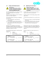
Abgleich Etikettenlichtschranke

Der Abgleich der Etikettenlichtschranke erfolgt über das

Offline-Menü des Druckers. Die Beschreibung finden Sie im

Abschnitt 2.4.2.

5.9

Abgleich Transferfolien-
lichtschranke

Der Abgleich der Transferfolienlichtschranke erfolgt über

das Offline-Menü des Druckers. Die Beschreibung finden

Sie im Abschnitt 2.4.3.

5.7

Justage Riemenspannung
Motor Hauptantrieb

Lebensgefahr!
Trennen Sie den Drucker vom Netz-
anschluss sonst besteht Lebensgefahr
durch spannungsführende Leiter im
Innern des geöffneten Druckers!

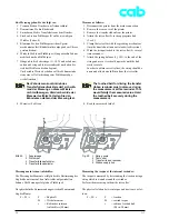
Zur Justage der Zahnriemenspannung gehen Sie wie folgt

vor:

1. Trennen Sie den Drucker vom Netzanschluss!

2. Demontieren Sie die Rückwand.

3. Lösen Sie die 4 Schrauben (2) der Befestigung des

Motors Hauptantrieb an der Montagewand.

4. Schwenken Sie den Motor Hauptantrieb von Hand so,

dass sich der Zahnriemen (1) zwischen Motor

Hauptantreib und Druckwalze straff spannt und ziehen

Sie die Schrauben (2) in dieser Motorstellung wieder

fest an.

5. Montieren Sie die Rückwand.

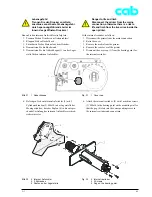
Bild 44

1 Zahnriemen
2 4 Schrauben

Fig. 44

1 Toothed belt
2 4 Screws

5.7

Adjusting the belt tension
of the main motor drive

Danger to life and limb
Disconnect the printer from the mains
connection, otherwise there is a risk to
life and limb from the live wires inside the
open printer.

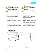
The tension of the toothed-belt is adjusted as follows:

1. Disconnect the printer from the mains connection.

2. Remove the rear cover of the printer.

3. Remove the 4 screws (2) holding the main motor drive

to the mounting wall.

4. Swivel the main motor drive by hand so that the

toothed belt (1) is taut between the main motor drive

and the print roller, then retighten the screws (2) with

the motor in this position.

5. Refit the rear cover of the printer.

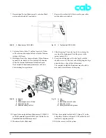
5.8

Adjusting the label edge sensor

The label edge sensor is aligned via the printer’s offline

menu. This adjustment is described in section 2.4.2.

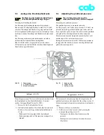
5.9

Adjusting the transfer ribbon
sensor

The transfer ribbon  sensor is adjusted via the printer’s offline
menu. This adjustment  is described in section 2.4.3.

Содержание A3

Страница 1: ...Transferdrucker Transfer Printer Serviceanleitung Service Manual Ausgabe Edition 3 02 ...

Страница 2: ...t to alter specifications without notice Données technique modifiables sans prévais Gesellschaft für Computer und Automations Bausteine mbH Co KG cab Produkttechnik GmbH Co KG Postfach 1904 D 76007 Karlsruhe Wilhelm Schickard Str 14 D 76131 Karlsruhe Telefon 49 0 721 66 26 00 Telefax 49 0 721 66 26 249 Web http www cabgmbh com e mail info cabgmbh com ...

Страница 3: ...nung Motor Hauptantrieb 58 5 8 Abgleich der Etikettenlichtschranke 58 5 9 Abgleich der Transferfolienlichtschranke 58 Table of Contents 1 Introduction 1 1 Scope of information 3 1 2 Important information 3 1 3 General safety instructions 4 1 4 Safe handling of electricity 5 1 5 Features 6 1 6 Package contents 7 1 7 Printer component location 8 1 8 Optional features 9 1 9 Device types 9 1 10 Techni...

Страница 4: ... Ersatzteilregister A11 A14 Blockschaltbild B1 Stromlaufpläne C1 C10 Bestückungspläne D1 D3 Stichwortverzeichnis 6 Trouble diagnosis and correction 6 1 Errors during printing 59 6 2 Failure of device functions 61 6 3 Permanently displayed hardware errors 62 Appendices List of Spare Parts A1 A Spare Parts Register A15 A18 Block Diagram B1 Circuit Diagrams C1 C10 Layout diagrams D1 D3 Index ...

Страница 5: ...ould be followed Example Note The two cooling angle screws are shorter 6 mm long 1 Einführung 1 1 Hinweise für den Benutzer Dieses Handbuch ist für das qualifizierte Service und Wartungspersonal vorgesehen Es beinhaltet technische Informationen die sich auf die Hardware und den mechanischen Teil des Etikettendruckers A3 beziehen Informationen zur Bedienung des Druckers finden Sie in der Bedienungs...

Страница 6: ...der Augen aufgrund der Arbeitsbedingungen Bringen Sie nach Ausführung der Wartungsarbeiten sämtliche Schutzvorrichtungen wie Abdeckungen Sicherheitshinweise und Erdungskabel wieder an Tauschen Sie fehlerhafte oder unbrauchbar gewordene Teile aus 1 3 General safety instructions Follow the general safety rules below Keep the area around the device clean at all times Avoid performing maintenance whic...

Страница 7: ... die andere Hand solange hinter dem Rücken oder stecken Sie diese in die Tasche Ein Stromschlag setzt einen geschlosse nen Stromkreis voraus Auf die oben beschriebene Weise wird verhindert dass ein Stromfluss über den eigenen Körper zustande kommt 1 4 Safe handling of electricity Follow the additional instructions below when handling electricity Repair testing and other work on electrical componen...

Страница 8: ...eaderscanbeconnected CompactFlash Card interface menu controlledprogramming printhead change between 203 dpi and 300 dpi without adjustment wide range power unit from 100 to 240 V no voltage changeover required 32 bit processor with 8 MB input memory wide range of fonts character sets and graphic elements available scaleable fonts allow for variety regarding their height and width with inverse ita...

Страница 9: ...cht zweckentsprechende Verpackung kann zur Beschädigung des Druckers führen Schützen Sie das Gerät ausrei chend vor Stoß 1 6 Package Contents As delivered the A3 Label Printer standard package includes 1 A3 Label Printer incl empty cardboard core mounted on ribbon take up hub and tear off plate to be mounted on the front 1 Rewind guide plate only for devices with an internal rewinder 1 power cord ...

Страница 10: ...er nur bei A3R 15 Hebel zur Druckkopfverriegelung 16 Knopf zur Justage des Transferfolienumlenkbleches 17 Stellring 18 Lasche Auszugssperre 19 Innensechskantschlüssel mit Griff Fig 1 1 Cover 2 CompactFlash slot 3 Display 4 Ribbon take up hub 5 Navigator pad with keys 6 Ribbon shield 7 Panel cover for peripheral connector 8 Tear off plate 9 Knob for adjusting printhead support 10 Ribbon supply hub ...

Страница 11: ...ow are optionally available for the A3 Label Printer External rewinder Cutter Present sensor Memory modules CompactFlash Card to 64 MB External Keyboard USB Interface expansion with RS 422 485 USB or Ethernet card EASYLABEL software for Windows 1 9 Device types A3 is produced in following types A3 203 with 203dpi printhead A3 203R with 203dpi printhead with internal rewinder A3 300 with 300dpi pri...

Страница 12: ...ppkern 38 1 bzw 40 mm mit Pappkern Wickeldurchmesser bis 145 mm 1 10 Technical Specifications Printhead Type Thermal Thermaltransferprinter Printhead Thickfilmtransferhead Printhead A3 203 203dpi 8dots mm resolution A3 300 300dpi 11 8dots mm Dots Line A3 203 832 A3 300 1280 Printing width A3 203 to 4 09 104 mm A3 300 to 4 26 108 4 mm Printingspeed A3 203 2 3 4 5 6 7 8 ips 50 75 100 125 150 175 200...

Страница 13: ...Textfelder max 250 Grafikelemente max 200 Bitmap Grafiken max 128 max 100 verschiedene Barcodefelder max 100 Transfer ribbon Inked side face in or face out on the roll Supply roll diameter up to 3 14 80 mm Core diameter 0 98 25 mm Width up to 4 48 114 mm Length up to 17 68 450 mm Label sensor Distanceto paperedge 4to57 5mm Materialrecognition Gapsensor see through Bottom reflectivesensor Electroni...

Страница 14: ...xicode QR Code Überwachung Test StoppdesDruck vorgangs bei Ende Transferfolie Ende Etiketten Endlosmaterial Druckkopf offen Fonts Available fonts 5 bitmap fonts incl OCR A and OCR B 3 vector fonts internally loadable SpeedoTM and True TypeTM fonts Character Sets Windows 1250 1251 1252 1253 1254 1255 1256 1257 DOS 437 737 775 850 852 862 864 866 869 Macintosh Roman EBCDIC 500 ISO 8859 1 8859 2 8859...

Страница 15: ...Transport 25 bis 70 C bei max 95 rel Luftfeuchtigkeit Lagerung 5 bis 40 C bei 5 bis 85 rel Luftfeuchtigkeit Testing facilities System test during power up include a printhead test short status display status printout font list device list printhead profile label profile test grid ASCII dump mode Status messages Printed length counter operating hours counter Miscellaneous Dimensions HxWxD 274 mm x ...

Страница 16: ...ei einge schaltetem Gerät erfolgen Detaillierte Angaben zu den erweiterten Funktionen erhalten Sie in den nächsten Abschnitten Bild 3 1 Schnittstelle Master USB 2 Serviceschlüssel Fig 3 1 Master USB interface 2 Service key 2 Expanded device functions for servicing 2 1 The Service key There is a service key for accessing special service functions which are not accessible to the operator Among other...

Страница 17: ...sor Abreißposition Rücktransport Pause Neudruck Fehler Neudruck Protokollfehler Der Parameter Protokollfehler ist nur dem Service mit gestecktem Serviceschlüssel zugänglich 2 2 Expanded functions in the Setup menu 2 2 1 Machine parameters A series of hardware parameters can be set in the Machine parameters sub menu This also includes the parameters for the optional components Cutter and Present se...

Страница 18: ... Sie nun das Untermenü Druckparam und schließlich den Parameter Protokollfehler an drücken Sie dann die Taste 5 Stellen Sie den Parameter nach Bedarf ein Bild 4 Aufruf Parameter Protokollfehler Fig 4 Call Protocol error parameter Protocol error The protocol error parameter is ON in the standard setting As a result the error message protocol error is displayed if the printer receives unknown or fau...

Страница 19: ...aste vom Zustand Bereit in das Offline Menü Drücken Sie die Tasten oder so oft bis das Menü Test erreicht ist und drücken Sie dann die Taste Wählen Sie nun die gewünschte Testfunktion 2 2 3 Interfaces The following parameters can be called or configured in the Interfaces submenu Character set and RS 232 If the optional interfaces Ethernet and RS 422 485 are installed then these are also shown for ...

Страница 20: ...Etikettenlichtschranke F Linienmuster zur Bewertung der Druckbildqualität Im Folgenden wird ein typischer Statusausdruck gezeigt 2 3 1 Status print The status print contains information about the printer configuration and the status The Status print will be printed with the heat level and the print speed set in the Setup menu With the service key inserted the status print also contains parameter s...

Страница 21: ...ON Bild 5 Statusausdruck Deutschland mit gestecktem Serviceschlüssel Fig 5 USA status printout with service key inserted A B C D F E OPTION OPTION OPTION Service Daten nur mit Schlüssel Service Data only with key ...

Страница 22: ...s USB Gerätes Class Kennziffer für die USB Geräteklasse Protokoll Kennziffer für die Art der Kommunikation mit dem USB Gerät Phase interner Wert für Debug Zwecke 2 3 2 Device list The most important hardware components installed in the printer and the connected optional devices are listed in the Device list submenu Please also refer to the Test Functions section of the A3 Label Printer Operating M...

Страница 23: ...21 A 3 Bild 6 Geräteliste Fig 6 Device list ...

Страница 24: ...Ereignisliste erreicht ist 4 Starten Sie den Ausdruck mit der Taste Der Ausdruck kann mit abgebrochen werden Bild 7 zeigt den Ausdruck einer Ereignisliste 2 3 3 Event list The A3 Label Printer stores the following events in the event list Hardware fault Printhead replacement with change of resolution Adjustment of the label sensor Adjustment of the transfer ribbon sensor Firmware updates Service c...

Страница 25: ...ge informiert der Servicezähler über die Drucklei stung seit dem letzten Rücksetzen Die Werte des Servicezählers werden nur bei gestecktem Serviceschlüssel im Statusausdruck angezeigt 2 4 Expanded functions in the Service menu In the Service menu the operator only has access to the Firmware update function The following functions are available after the service key has been inserted Firmware updat...

Страница 26: ...sausdruck vornehmen Bild 8 Auszug aus dem Statusausdruck Daten des Servicezählers Fig 8 Extract from the status data printout of the service counter Servicezähler auf Null gesetzt Service counter set to zero Servicezähler vor dem Rücksetzen Service counter before reset The service counter is reset as follows 1 Switch from Online mode to the Offline menu by pressing the key 2 Keep pressing the or k...

Страница 27: ...ederholung des Abgleichs auf liegt u U ein Defekt an folgenden Baugruppen vor Etikettenlichtschranke Anschlusskabel der Etikettenlichtschranke oder Leiterplatte CPU Bild 9 Aufruf der Funktion Adjust gap sensor Fig 9 Calling the Adjust gap sensor function 2 4 2 Adjusting the label edge sensor This function enables the label edge sensor to be adjusted This is necessary when the label edge sensor its...

Страница 28: ...ruppen vor Leiterplatte CPU Lichtleiter 5943179 oder Verschmutzung der Taktscheibe am Transferfolienab wickler Bild 10 Aufruf Funktion Adjust ribbon sensor Fig 10 Calling the Adjust ribbon sensor function 2 4 3 Adjusting the transfer ribbon sensor This function enables the transfer ribbon sensor to be aligned This becomes necessary when the ribbon supply hub or the CPU PCB are changed or removed I...

Страница 29: ...ompactFlash Speicherkarte informieren Sie sich bitte in der Bedienungsanleitung im Abschnitt Speicherkarten Bild 12 Aufruf Funktion Save NVRAM Fig 12 Calling the Save NVRAM function Bild 11 Einschieben der CF Karte Fig 11 Inserting the CF card 2 4 4 Saving on the NVRAM The Save NVRAM function is used to save a printer configuration on a CompactFlash memory module This function is only accessible w...

Страница 30: ...rgang zu wieder holen Bei erneutem Fehler müssen die Konfigurationsparameter des Druckers einzeln neu eingestellt werden Bild 13 Aufruf Funktion Save NVRAM Fig 13 Calling the Save NVRAM function 2 4 5 Loading the NVRAM The Load NVRAM function is used to reload a previously saved printer configuration from a CompactFlash memory module This function is only accessible with the service key in serted ...

Страница 31: ...zenden scheuernden oder harten Gegenstände zur Reinigung des Druckkopfs Berühren Sie die Glasschutzschicht des Druckkopfs möglichst nicht mit bloßen Händen 3 Maintenance Unplug the power cord from the power source before starting any maintenance work The printer requires little maintenance It is important to clean the thermal printhead regularly This guarantees a consistently good printed image an...

Страница 32: ...hmen Sie Etiketten und Transferfolie aus dem Drucker 4 Entfernen Sie alle Ablagerungen mit Spiritus und einem weichen Tuch von den nun zugänglichen Oberflächen Clean the printhead as follows 1 Disconnect the printer from the mains connection 2 Open the printhead as far as possible 3 Remove the media and ribbon from the printer 4 Clean the surface of the printhead with a cleaning pen or use a cotto...

Страница 33: ...nkten Lappen 6 Schieben Sie die Lichtschranke in ihre Ausgangs position zurück Bild 14 Etikettenlichtschranke reinigen Fig 14 Cleaning the label edge sensor 5 Clean the label edge sensor and in particular the sensors 3 with a soft brush or a cloth dipped in alcohol 6 Slide the label edge sensor back into its original position ...

Страница 34: ...lkopf 2 mm Sechskant Winkelschrauben dreher mit Kugelkopf 2 5 mm Seegerringzange ZGG 0 Seegerringzange ZGG 1 Federwaage 10 N Federwaage 25 N 4 Replacing Assembly Units Danger to life and limb Disconnect the printer from the mains connection before starting any work to change assembly units otherwise there is a risk to life and limb from the live wires inside the open printer 4 1 List of recommende...

Страница 35: ...echskantschlüssel 2 5 mm mit Griff 7 Bild 17 Bild 16 1 Druckkopf 203 und 300 dpi und 2 Zwischenplatte 3 Druckkopf Kennzeichnung 4 Schrauben Fig 16 1 Printhead 203 and 300 dpi and 2 Headplate 3 Printhead identification 4 Screws Bild 15 Deckel demontieren Fig 15 Removing the cover 4 3 Replacing the printhead The printer is designed so that the printhead can be replaced without making any readjustmen...

Страница 36: ...n Sie die Feststellschraube 6 vollständig an ohne die Schraube zu überdrehen Bild 18 Druckkopf und Steckverbinder Fig 18 Printhead and plug connectors Bild 17 Druckkopf und Feststellschraube Fig 17 Printhead and locking screw 5 Swing the lever 5 figure 17 clockwise as far as it will go and in this way lift the printhead assembly up 6 Pull the printhead 1 figure 17 off the pins 11 in the printhead ...

Страница 37: ...eihenfolge a b an 10 Montieren Sie das Abreißblech 2 Befestigen Sie das Abreißblech mit den Schrauben 3 Bild 20 Druckwalze und Zwischenwelle Fig 20 Print roller and shaft Bild 19 Druckwalze und Lagerung Fig 19 Print roller and bearing assembly 4 4 Replacing the print roller Replace the print roller as follows 1 Disconnect the printer from the mains connection 2 Lift the printhead up and remove the...

Страница 38: ...ht herausfallen Bild 21 1 Rutschkupplung Abwickler Transferfolie 2 Rutschkupplung Aufwickler Transferfolie 3 Rutschkupplung interner Aufwickler Option Fig 21 1 Slip clutch for ribbon take up hub 2 Slip clutch for ribbon rewinder 3 Slip clutch for internal rewinder option 4 5 Replacing the slipping clutches Danger to life and limb Disconnect the printer from the mains connection otherwise there is ...

Страница 39: ...e 5 bis zum Anschlag auf mäßige Handkraft anwenden Bild 22 4 Rändelmutter 5 Nabe 6 2 Gewindestifte 7 Kupplungsscheiben 8 Mitnehmer 9 6 Federn Fig 22 4 Knurled nut 5 Hub 6 2 Threaded pins 7 Clutch plates 8 Driver 9 6 Springs Bild 23 Nabenmontage Fig 23 Hub assembly 7 Tighten the threaded pin 6 8 Apply hand pressure to the clutch plates and set the distance between the driver 8 and the cast surface ...

Страница 40: ... und damit ebenfalls die Rückstellwirkung der Feder mindern 10 Stellen Sie die Kupplung gemäß Abschnitt 5 5 ein und montieren Sie die Rückwand Three conditions have to be fulfilled in this state pre tensioned clutch The driver 8 must be at a distance of about 0 5 mm from the cast surface 10 The spring 12 must have a reset effect for the driver 8 in both directions of rotation The distance between ...

Страница 41: ...e die Rückwand Bild 24 4 Rändelmutter 6 Gewindestifte 9 6 Federn 16 Nase 17 Aussparung Nut 18 Riemenrad A Nuttiefe Fig 24 4 Knurled nut 6 Threaded pin 9 6 Springs 16 Lug 17 Slot 18 Belt pulley A Slot depth 9 Set the clutch according to section 5 5 and refit the rear cover of the printer 4 6 Replacing the label edge sensor Check for dirt before making the exchange Danger to life and limb Disconnect...

Страница 42: ... 2 4 2 durch 13 Montieren Sie die Rückwand Bild 26 1 Etikettenlichtschranke 4 Flexband Fig 26 1 Label edge sensor 4 Flexband Bild 25 1 Etikettenlichtschranke 2 Schrauben 3 Lagerplatine Fig 25 1 Label edge sensor 2 Screws 3 Plate 4 Slide the label edge sensor 1 as far as it will go in the direction of the rear of the A3 5 Pull the flexband connector 4 out of the connecting plug on the label edge se...

Страница 43: ...Fig 27 1 2 Screws rear side 2 2 Screws into CPU PCB chassis 7 Schwenken Sie die Leiterplatte CPU um 90 nach unten und lösen Sie die unteren Steckverbinder ab Damit ist die Leiterplatte CPU demontiert 4 7 Replacing the CPU PCB Danger to life and limb Disconnect the printer from the mains connection otherwise there is a risk to life and limb from the live wires inside the open printer Replace the CP...

Страница 44: ...schluss 6 Druckkopf Logikanschluss 7 Motor 8 Kopfverriegelung 9 USB Peripherie 10 USB Peripherie 11 Bedienfeld Fig 28 3 Label edge sensor 4 Low voltage input from power pack 5 Printhead power connector 6 Printhead logic connector 7 Motor 8 Head lock 9 USB peripherals 10 USB peripherals 11 Control panel Fitting a new CPU PCB 1 Insert the plugs 3 to 6 into the underside of the CPU PCB 2 Swivel the P...

Страница 45: ...nnung von bis zu 380 V Diese Spannung klingt innerhalb einer Minute nach dem Abschalten des Druckers bzw Netzteils auf ungefährli che Werte 42 V ab Während der Entladezeit des Kondensators Elko von ca einer Minute besteht jedoch die Gefahr auch nach dem Abschalten des Netzteils Bitte beachten Sie diese Gefährdung Replace the power unit as follows 1 Disconnect the printer from the mains connection ...

Страница 46: ...new power unit 10 Adjust the transfer ribbon sensor as described in section 2 4 3 as the position may have changed as a result of the removal and fitting of the CPU PCB 4 9 Installing the internal rewinder The A3 203 and A3 300 printer models are supplied without an internal rewinder However from serial no 1001 the devices are capable of being upgraded with an internal rewinder For this purpose th...

Страница 47: ...lers verdreh sicher einrastet Bild 31 1 Abdeckkappe Fig 31 1 Cover cap Bild 32 2 Interner Aufwickler 3 3 Schrauben 4 Zapfen an der Lagerstelle Fig 32 2 Internal rewinder 3 3 Screws 4 Peg on the bearing point Danger to life and limb Disconnect the printer from the mains connection otherwise there is a risk to life and limb from the live wires inside the open printer Fit the internal rewinder as fol...

Страница 48: ...lt tensioner with roller 9 Shoulder screw 10 Spring retainer with groove Bild 33 5 Zahnriemen 120 0 MXL Fig 33 5 Toothed belt 120 0 MXL 7 Demontieren Sie den Zahnriemen 5 zwischen Druck walze und Aufwickler Transferfolie 7 Remove the toothed belt 5 between the print roller and the ribbon rewind hub 8 Slide the spring 7 onto the lug 6 In so doing the rear leg of the spring must lie in the groove in...

Страница 49: ...ler Transferfolie 12 Zahnriemen 265 MXL 13 Riemenrad Druckwalze 14 Riemenrad interner Aufwickler Fig 35 11 Belt pulley of transfer ribbon rewinder 12 Toothed belt 265 MXL 13 Belt pulley of print roller 14 Belt pulley of internal rewinder ...

Страница 50: ... Justierschrauben 2 zunächst gleichmä ßig verdrehen bis eine Seite des Druck bildes optimiert ist dann die Seite mit der schlechteren Druckbildqualität justieren 5 Adjustments Settings and Alignments 5 1 Adjusting the printhead The printhead is attached to the holding bracket by retaining pins which have been exactly aligned in the manufacturer s works This setting ensures correct positioning when...

Страница 51: ...ung angebracht und nicht als exakte Referenz für bestimmte Etikettenbreiten anzusehen Bild 36 1 Feststellschraube für Druckkopf 2 Justierschrauben 3 Druckkopf Fig 36 1 Printhead locking screw 2 Adjustment screws 3 Printhead 4 Open and close the printhead after each adjustment step Only then does the adjustment become effective 5 Tighten the locking screw 1 by hand 6 Make a test print e g black bar...

Страница 52: ...zu Faltenbildungen im Transferfolienlauf führen Bild 37 1 Druckkopf 2 Kopfabstützung 3 Rändelschraube 4 Langloch Fig 37 1 Printhead 2 Printhead support 3 Knurled knob 4 Elongated hole 2 Position 1 is recommended for wide labels In this position the printhead support 2 is completely disabled 3 For narrow labels loosen the knurled knob 3 and slide it slowly towards position 5 This lifts the outside ...

Страница 53: ...rsinn verringert den Andruck Bild 38 1 Federwaage 2 2 Teflonband Streifen 3 Einstellschrauben Fig 38 1 Spring scale 2 Teflon ribbon 3 Setting screws 5 3 Adjusting the printhead pressure The printhead pressure must be measured without the printhead support Measuring the printhead pressure The printhead pressure is measured indirectly For this purpose two Teflon strips item no 553 0687 are placed be...

Страница 54: ...nbildung ist die Transferfolie an der Kante zu straffen von der die Faltenbildung ausgeht Bild 39 1 Transferfolie 2 Transferfolienumlenkblech 3 Skala 4 Rändelschraube Fig 39 1 Transfer ribbon 2 Ribbon shield 3 Scale 4 Knurled knob 5 4 Adjusting the transfer ribbon If wrinkles appear in the transfer ribbon 1 which cause an inconsistent printed image the ribbon shield 2 can be adjusted to remove the...

Страница 55: ...rte Transferfolienaufwickler MAuf 19 25 5 Ncm FAuf 6 3 8 5 N Transferfolienabwickler MAb 4 4 5 Ncm FAb 1 3 1 5 N 5 5 Adjusting the hub torques Danger to life and limb Disconnect the printer from the mains connection otherwise there is a risk to life and limb from the live wires inside the open printer The transfer ribbon rewinder and the internal rewinder are coupled to the main drive by a slippin...

Страница 56: ...er zu drehen beginnt Um korrekte Werte zu erhalten soll die Schnur minde stens eine volle Umdrehung vom Prüfkörper abge wickelt werden Der Zahnriemen zum Antrieb des Transferfolienaufwicklers darf sich wäh rend der Messung an diesem Wickler nicht mitbewegen Hierdurch würde der Messwert verfälscht Halten Sie den Zahnriemen während der Messung fest 8 Messwert F ablesen Measure as follows 1 Disconnec...

Страница 57: ... ablesen Measure as follows 1 Disconnect the printer from the mains connection 2 Remove the rear cover of the printer 3 Remove all label stock from the printer 4 Wind the string 5 several times around the internal rewind hub 6 5 Attach the spring balance 1 25 N to the end of the string and move it vertically upwards until the hub starts to rotate Do not take a reading off the spring balance scale ...

Страница 58: ...plug the power cable 2 Remove the rear cover 3 Adjust the winding torque by turning the knurled nut of the corresponding clutch 7 8 9 Turning it clockwise increases the torque Turning it anti clockwise decreases the torque The numbers on the knurled nut are not setting values they are for orientation only 4 Repeat the measuring 5 Refit the rear cover after completing the adjustment Bild 42 7 Einst...

Страница 59: ... zu erneuern 6 Montieren Sie die Rückwand Bild 43 1 Kopfschalter 2 Schraube Zwischenträger 3 Schaltbügel Fig 43 1 Head switch 2 Intermediate holder screw 3 Switch lever 5 6 Adjusting the head switch Danger to life and limb Disconnect the printer from the mains connection otherwise there is a risk to life and limb from the live wires inside the open printer This switch prevents printing operations ...

Страница 60: ... Sie die Schrauben 2 in dieser Motorstellung wieder fest an 5 Montieren Sie die Rückwand Bild 44 1 Zahnriemen 2 4 Schrauben Fig 44 1 Toothed belt 2 4 Screws 5 7 Adjusting the belt tension of the main motor drive Danger to life and limb Disconnect the printer from the mains connection otherwise there is a risk to life and limb from the live wires inside the open printer The tension of the toothed b...

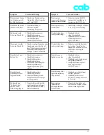
Страница 61: ...ge sensor dirty clean label edge sensor 3 Label edge sensor is not adjusted e g after replacing the CPU PCB carry out the adjust ment 4 Label edge sensor defective replace sensor 1 Transfer ribbon loaded in correctly check if coated side is facing towards the paper 2 Unsuitable ribbon paper com bination leads to insufficient friction between paper and ribbon choose different transfer ribbon Ursach...

Страница 62: ...Setup ändern 1 Transferfolienrolle am Ab wickler nicht festgeklemmt Abwickler dreht sich nicht Rolle festklemmen Symptom Printer prints sequence of characters instead of label format Printer prints every second label Vertical white lines in the printed image Vertical white lines in the printed image Printed image is lighter on one side Printed image is too light after replacing the printhead Error...

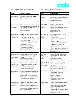
Страница 63: ...r Schnittstellen konfiguration von Drucker und Computer prüfen 2 Überprüfung des Interfacekabels 3 Bei vollständigem Funktionsausfall Leiterplatte CPU tauschen 1 Prüfen ob Peripheriegerät durch Programmierung aktiviert ist 2 Kabel USB Peripherie prüfen ggf tauschen 3 Überprüfung des Peripheriegerätes 4 LP CPU austauschen Possible Solutions 1 Mechanical check of the gears and belts replace damaged ...

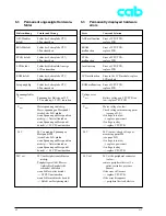
Страница 64: ...er Aufwickler Spendelicht schranke abziehen wenn Fehler weiter besteht LP CPU austauschen wenn Fehler nicht mehr besteht Defekt am Peripheriegerät 6 3 Permanent angezeigte Hardware fehler 6 3 Permanently displayed hardware errors Error ADC malfunction dRAM malfunction FPGA malfunction Invalid setup LCD malfunction ROM malfunction Voltage error VBAT VMOT 24V 24V ext Cause and Solution Error of CPU ...

Страница 65: ...ehler weiter besteht LP CPU austauschen wenn Fehler nicht mehr besteht Schnittstellenwandler ungeeignet Error 5V ext Cause and Solution 5V at the Centronics interface too low an interface converter with a current consumption which is too high may have been connected remove interface converter if the error still occurs replace CPU PCB if the error disappears unsuitable interface converter ...

Страница 66: ...64 A 3 ...

Страница 67: ...Druckkopfverriegelung 6 Druckwalzenbaugruppe 7 Getriebe Rollenhalter 8 Transferbandwickler 9 InternerAufwickler Spare Parts List Application The following spare parts list applies for the A3 printers starting from serial number 1001 The spare parts for the printers up to serial number 999 are included in Edition 12 01 of the spare parts list References for Spare Parts Ordering 1 Please address spa...

Страница 68: ...raube DIN7984 M4x10 galZn 3 32 5943160 Blende 2 1 33 5902241 Zylinderschraube DIN7984 M4x10 galZn 2 34 5943006 Deckel oben 1 35 5943007 Deckel unten 1 36 5943081 Bedienfeld mont 1 BG BG Baugruppe No Part No Description Pieces 1 5902241 Screw DIN7984 M4x10 galZn 2 2 5943009 Cover Plate 1 3 5901574 Cable Clamp ACC38 A 2 4 5902241 Screw DIN7984 M4x10 galZn 4 5 5550122 Main Board A3 PCB CPU 1 6 594313...

Страница 69: ...DIN7984 M4x10 galZn 2 11 5902358 Zylinderschraube DIN7984 M4x6 8 8 galZn 1 12 5903011 Zahnscheibe DIN6797 A4 3 galZn 1 13 5903003 Scheibe DIN125 A4 3 galZn 1 No Part No Description Pieces 1 5943107 Cable 1 2 5902241 Screw DIN7984 M4x10 galZn 2 3 5901509 Cable Clamp No 7422770 4 4 5902241 Screw DIN7984 M4x10 galZn 3 5 5943197 Cover Plate 1 6 5902358 Screw DIN7984 M4x6 8 8 galZn 2 7 5943106 Power Su...

Страница 70: ...988 4x8x0 2 1 30 5943155 Kopfschraube 1 31 5903525 Sicherungsscheibe DIN6799 4 galZn 1 32 5946100 Kopfbaugruppe 1 BG 1 A3 203 2 A3 203R 3 A3 300 4 A3 300R BG Baugruppe No Part No Description Pieces 1 5942394 Printhead Cable 1 1 2 5942395 Printhead Cable 2 1 3 5942370 Printhead 203dpi Type 4203 1 1 2 3 5942371 Printhead 300dpi Type 4300 1 3 4 4 5943052 Bushing 1 5 5902007 Screw DIN912 M3x6 8 8 galZ...

Страница 71: ...1320 506 00 1 13 5946112 Profil oben 1 14 5943136 Schwenkwelle 1 15 5943114 Lagerplatine oben 1 16 5902241 Zylinderschraube DIN7984 M4x10 galZn 4 17 5943023 Knopf 1 No Part No Description Pieces 1 5903521 Snap Ring DIN471 A6 1 2 5943053 Plate Printhead lock unlock mount 1 3 5902399 Screw KA22x12 WN1412 galZn 2 4 5942386 Switch 1 5 5902241 Screw DIN7984 M4x10 galZn 1 6 5943152 Plate 1 7 5903521 Sna...

Страница 72: ...5 20 5902025 EJOT PT Schraube KB30x6 WN1412 galZn 4 5 21 5943174 Spendekante mont 1 5 2 A3 203R 4 A3 300R 5 Teil der Option Spendelichtschranke PS1 No Part No Description Pieces 1 5917430 Flex Cable 6 pin R1 500mm 1 2 5902241 Screw DIN7984 M4x10 galZn 1 3 5902348 Screw DIN7984 M4x16 8 8 galZn 3 4 5943125 Axle 1 5 5943025 Media Guide Ring 1 6 5942384 Label Sensor Assy 1 7 5943148 Lower Profile 1 8 ...

Страница 73: ...r kpl 1 21 5902655 Rändelschraube M3x20 4 8 galZn 1 22 5903004 Scheibe DIN125 A3 2 galZn 1 23 5943021 Führung 1 24 5902505 Sechskantmutter DIN934 M3 8 galZn 1 1 A3 203 2 A3 203R 3 A3 300 4 A3 300R No Part No Description Pieces 1 5905196 Belt 120 0MXL 037 1 1 3 2 5905354 Belt 265MXL 037 1 2 4 3 5903516 Snap Ring DIN471 8 galZn 1 2 4 4 5530554 Belt Roller 1 2 4 5 5943031 Screw 1 2 4 6 5943029 Belt T...

Страница 74: ...3036 Teller Abwickler 1 22 5943058 Aufwickler Transfer 1 BG 23 5943059 Abwickler Transfer 1 BG BG Baugruppe Stückzahl nach Bedarf zur Minimierung des Lagerspiels No Part No Description Pieces 1 5943086 Brake 1 2 5903035 Washer DIN988 8x14x1 0 2 3 5943048 Spring 1 4 5903516 Snap Ring DIN471 8 galZn 2 5 5903038 Washer DIN988 8x14x0 2 2 6 5533968 Four Disk Slipping Clutch Part 1 1 7 5943045 Gear 42 1...

Страница 75: ...943060 Interner Aufwickler IR1 1 BG 1 A3 203 2 A3 203R 3 A3 300 4 A3 300R BG Baugruppe Stückzahl nach Bedarf zur Minimierung des Lagerspiels No Part No Description Pieces 1 5533969 Eight Disk Slipping Clutch Part 1 1 2 4 2 5943045 Gear 42 12 1 2 4 3 5903102 Washer 30x8 4x1 25 galZn 1 2 4 4 5903516 Snap Ring DIN471 8 galZn 2 2 4 5 5903038 Washer DIN988 8x14x0 2 1 2 4 6 5943064 Flange 1 2 4 7 590302...

Страница 76: ... Nr 7422770 4 A3 3 5901574 Kabelhalter ACC38 A 2 A2 3 5901583 Kabelclip ACC19 A M 3 A2 11 5902007 Zylinderschraube DIN912 M3x6 8 8 galZn 1 A4 5 5902009 Zylinderschraube DIN912 M3x12 8 8 galZn 1 A4 8 5902025 EJOT PT Schraube KB30x6 WN1412 galZn 4 A6 20 5 5902040 EJOT PT Schraube KB25x8 WN1411 galZn 4 A2 17 5902044 EJOT PT Schraube KB40x10 WN1412 galZn 4 A7 9 5902129 EJOT PT Schraube KB22x6 WN1412 g...

Страница 77: ...alZn 1 A8 8 1 A9 3 2 4 5903106 Passscheibe DIN988 6x12x1 1 A4 11 5903505 Sicherungsscheibe DIN6799 5 galZn 1 A4 25 5903516 Sicherungsring DIN471 8 galZn 1 A7 3 2 4 1 A7 10 2 A7 12 2 A8 4 2 A8 11 2 A9 4 2 4 5903521 Sicherungsring DIN471 A6 1 A5 1 1 A5 7 2 A5 9 5903525 Sicherungsscheibe DIN6799 4 galZn 1 A4 31 5904542 Gewindestift DIN914 M5x20 2 A4 28 5905014 Druckfeder D 144C 2 A4 15 5905098 Druckf...

Страница 78: ... 6 2 4 5943031 2 Ansatzschraube 1 A7 5 2 4 5943032 4 Abdeckkappe 1 A9 17 1 3 5943035 1 Teller Aufwickler 1 A8 14 5943036 1 Teller Abwickler 1 A8 21 5943038 2 Zwischenwelle kpl 1 A7 14 5943045 2 Riemenrad 42 12 kpl 1 A8 7 1 A9 2 2 4 5943046 5 Welle Aufwickler 1 A9 8 2 4 5943048 3 Drehfeder 1 A8 3 5943052 1 Lagerbuchse 1 A4 4 5943053 1 Kurve mont 1 A5 2 5943057 2 Welle Transfer 2 A8 13 5943058 2 Auf...

Страница 79: ...ckstück 2 1 A4 9 5943182 1 Wärmeleitfolie 2 A2 7 5943186 1 LP Spendeelektronik kpl 1 A6 19 5 5943188 1 Gummischeibe 1 A4 10 5943192 1 Abdeckblech 1 A5 11 5943193 3 Schale 122 3mm D 38 1 2 A9 11 2 4 5943194 1 Spannkonus 4 1 A9 9 2 4 5943197 1 Abdeckblech 1 A3 5 5946100 1 Kopfbaugruppe 1 A4 32 5946101 1 Kopfwinkel kpl 1 A4 14 5946103 1 Feder 1 1 A4 22 5946104 1 Feder 2 1 A4 23 5946105 1 Lagerwinkel ...

Страница 80: ...IN625 F608 ZZ 2 A7 13 4 A8 9 5901509 Cable Clamp No 7422770 4 A3 3 5901574 Cable Clamp ACC38 A 2 A2 3 5901583 Cable Holder 3 A2 11 5902007 Screw DIN912 M3x6 8 8 galZn 1 A4 5 5902009 Screw DIN912 M3x12 8 8 galZn 1 A4 8 5902025 Screw KB30x6 WN1412 galZn 4 A6 20 5 5902040 Screw KB25x8 WN1411 galZn 4 A2 17 5902044 Screw KB40x10 WN1412 galZn 4 A7 9 5902129 Screw KB22x6 WN1412 galZn cB 3 A2 14 5902241 S...

Страница 81: ... 2 4 5903106 Washer DIN988 6x12x1 1 A4 11 5903505 E Ring DIN6799 5 galZn 1 A4 25 5903516 Snap Ring DIN471 8 galZn 1 A7 3 2 4 1 A7 10 2 A7 12 2 A8 4 2 A8 11 2 A9 4 2 4 5903521 Snap Ring DIN471 A6 1 A5 1 1 A5 7 2 A5 9 5903525 E Ring DIN6799 4 galZn 1 A4 31 5904542 Set Screw DIN914 M5x20 2 A4 28 5905014 Spring D 144C 2 A4 15 5905098 Spring D 117H 50 1 A4 18 5905196 Belt 120 0MXL 037 1 A7 1 1 3 590532...

Страница 82: ... Belt Tension Arm 1 A7 6 2 4 5943031 2 Screw 1 A7 5 2 4 5943032 4 Cape Rewind Hole 1 A9 17 1 3 5943035 1 Wall Spacer Rewinder 1 A8 14 5943036 1 Wall Spacer Unwinder 1 A8 21 5943038 2 Shaft 1 A7 14 5943045 2 Gear 42 12 1 A8 7 1 A9 2 2 4 5943046 5 Shaft 1 A9 8 2 4 5943048 3 Spring 1 A8 3 5943052 1 Bushing 1 A4 4 5943053 1 Plate Printhead lock unlock mount 1 A5 2 5943057 2 Shaft 2 A8 13 5943058 2 Rib...

Страница 83: ...sor Electronics 1 A6 19 5 5943188 1 Rubber Washer 1 A4 10 5943192 1 Cover Plate 1 A5 11 5943193 3 Rewind Spindle External Shell 2 A9 11 2 4 5943194 1 Rewinder Wall Plate 1 A9 9 2 4 5943197 1 Cover Plate 1 A3 5 5946100 1 Printhead Carriage Assy 1 A4 32 5946101 1 Printhead Mounting Bracket 1 A4 14 5946103 1 Plate Spring 1 1 A4 22 5946104 1 Plate Spring 2 1 A4 23 5946105 1 L Bracket with Axle 1 A4 24...

Страница 84: ...Index 02 01 23 B1 A3 Anlage B Blockschaltbild Appendix B Block Diagram ...

Страница 85: ...Index 02 01 23 C1 A3 Anlage C Stromlaufplan Leiterplatte CPU CPU Takt Uhr BDM Appendix C Circuit Diagram Mainboard PCB CPU CPU Clock Timer Clock BDM ...

Страница 86: ...Index 02 01 23 C2 A3 Anlage C Stromlaufplan Leiterplatte CPU Centronics Interface Slot RS 232 Appendix C Circuit Diagram Mainboard PCB CPU Centronics Interface Slot RS 232 ...

Страница 87: ...Index 02 01 23 C3 A3 Anlage C Stromlaufplan Leiterplatte CPU dRAM Flash Appendix C Circuit Diagram Mainboard PCB CPU dRAM Flash ...

Страница 88: ...Index 02 01 23 C4 A3 Anlage C Stromlaufplan Leiterplatte CPU Druckkopfanschluss Appendix C Circuit Diagram Mainboard PCB CPU Printhead Connection ...

Страница 89: ...Index 02 01 23 C5 A3 Anlage C Stromlaufplan Leiterplatte CPU FPGA History RAM Appendix C Circuit Diagram Mainboard PCB CPU FPGA History RAM ...

Страница 90: ...Index 02 01 23 C6 A3 Anlage C Stromlaufplan Leiterplatte CPU Netzteil Antrieb Appendix C Circuit Diagram Mainboard PCB CPU Power Supply Motor Driver ...

Страница 91: ...Index 02 01 23 C7 A3 Anlage C Stromlaufplan Leiterplatte CPU Sensoren AD Wandler Druckkopfverriegelung Appendix C Circuit Diagram Mainboard PCB CPU Sensors AD Converter Printhead Lock Sensor ...

Страница 92: ...Index 02 01 23 C8 A3 Anlage C Stromlaufplan Leiterplatte CPU USB Host Appendix C Circuit Diagram Mainboard PCB CPU USB Host ...

Страница 93: ...Index 02 01 23 C9 A3 Anlage C Stromlaufplan Leiterplatte Bedienfeld 1 Appendix C Circuit Diagram PCB Control Panel 1 ...

Страница 94: ...Index 02 01 23 C10 A3 Anlage C Stromlaufplan Leiterplatte Bedienfeld 2 Appendix C Circuit Diagram PCB Control Panel 2 ...

Страница 95: ...02 01 23 D1 A3 Anlage D Belegungsplan Leiterplatte CPU Bestückungsseite Appendix D Layout Diagram Mainboard PCB CPU Component s side ...

Страница 96: ...eiterplatte CPU Lötseite Appendix D Layout Diagram Mainboard PCB CPU Soldering side 1 2 3 4 5 6 7 8 9 Wichtige Messpunkte Important Measuring Points 1 24 V 2 GND 3 VMOT 4 24 V ext Peripherals 5 3 3 V 6 5 V 7 2 5 V 8 5 V ext Centronics 9 VBAT ...

Страница 97: ...tte Bedienfeld 1 Appendix D Layout Diagram PCB Control Panel 1 Anlage D Belegungsplan Leiterplatte Bedienfeld 2 Appendix D Layout Diagram PCB Control Panel 2 Bestückungsseite Component s side Lötseite Soldering side Bestückungsseite Component s side ...

Страница 98: ...6 Einstellung Kupplung Transferfolienabwickler 56 Einstellung Kupplung Transferfolienaufwickler 56 Einstellungen 48 Elektrofachkraft 5 Elektronik 11 Ereignisliste 17 22 Erweiterungskarte Schnittstellen 20 Etiketten 10 Etikettenlichtschranke abgleichen 25 Etikettenlichtschranke wechseln 39 Etikettenprofil 17 Etikettensensor 11 Etikettentlichtschranke reinigen 30 Index A A3 parts 8 Adjust gap sensor...

Страница 99: ...inthead pressure adjustment 51 Printheadprofile 17 Printhead support setting 49 Printhead adjust 48 Printhead cleaning 29 Printhead replacement 33 Protocolerror 16 Q Qualified and trained electrician 5 F Fehlerbeseitigung 59 Fehlersuche 59 Firmware Updates 22 FlashCard 20 Fonts 11 G Geräteeinstellungen 15 Gerätefunktionen Ausfall 61 Geräteliste 17 20 Gerätetypen 9 Grafik 12 H Hardware Fehler 22 62...

Страница 100: ...USB device class 20 USB devices installed 20 USB master interface 14 W Wide range power unit 6 R Rändelmutter Kupplung 36 Reinigung 29 Riemenspannung Motor Hauptantrieb 58 Rücksetzen der Servicezähler 22 Rutschkupplungen 36 Rutschkupplungen wechseln 36 S Schnittstelle Master USB 14 Schnittstellen 11 Schnittstellen Option 11 Schnittstellen Erweiterungskarte 20 Schriften 11 Schriftenliste 17 Serienn...

Страница 101: ...Index A3 ...

Отзывы: