48
A 3
5
Justagen, Einstellungen und
Abgleiche
5.1
Justage des Druckkopfes
Der Druckkopf ist am Aufnahmewinkel auf werksseitig
genau ausgerichteten Haltestiften befestigt.
Diese Einstellung gewährleistet ein korrektes Positionieren
von Ersatzdruckköpfen oder bei Wechsel auf einen Druck-
kopf mit anderer Auflösung.
In der Regel ist eine Neujustage nach einem Druckkopf-
wechsel nicht erforderlich.
Nach einer Demontage der gesamten Druckkopfbaugruppe
ist es notwendig die Haltestifte und damit den Druckkopf
neu zu justieren!
Für optimale Druckergebnisse muss die
Heizzeile des Druckkopfes exakt zur
Druckwalze ausgerichtet sein!
Die herstellerseitige Voreinstellung kann bei Bedarf korri-
giert werden!
Ein dejustierter Druckkopf führt zu Mängeln in der
Druckbildqualität!
Es können folgende Mängel entstehen:
Druckbild zu hell/Druckbild fleckig,
Druckbild einseitig aufgehellt.
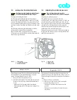
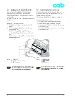
Justieren Sie den Druckkopf wie folgt:
Belassen Sie das Material im Drucker. Der Druckkopf ist
verriegelt.
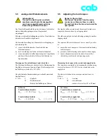
1. Führen Sie die Druckkopfjustage bei deaktivierter
Kopfabstützung (Abschnitt 5.2) aus.
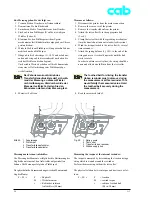
2. Lösen Sie die Feststellschraube (1) um eine halbe
Umdrehung. Dies ist ausreichend, um den Druckkopf
(3) nach vorn und hinten verschieben zu können.
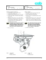
3. Verschieben Sie durch Drehen der Schrauben (2) den
Druckkopf (3) unter folgenden Bedingungen:
- möglicher Verstellweg 2,5 mm,
- Drehen im Uhrzeigersinn verschiebt Druckkopf
nach hinten (0,5 mm pro Umdrehung),
- nur kleine Verstellungen vornehmen
(Viertelumdrehungen)!
Justierschrauben (2) zunächst gleichmä-
ßig verdrehen, bis eine Seite des Druck-
bildes optimiert ist, dann die Seite mit der
schlechteren Druckbildqualität justieren.
5
Adjustments, Settings and
Alignments
5.1
Adjusting the printhead
The printhead is attached to the holding bracket by retaining
pins which have been exactly aligned in the manufacturer’s
works.
This setting ensures correct positioning when replacing a
printhead or changing to a printhead with a different
resolution.
As a rule, it is not necessary to readjust after a printhead
change.
After removing the entire printhead assembly, it is necessary
to readjust the retaining pins and thus the printhead.
For optimal print results, the printhead
heat strip must be exactly aligned with
the print roller.
The manufacturer’s pre-setting may be corrected if
necessary.
A maladjusted printhead leads to a poor quality printed
image.
The following defects may arise:
Printed image too light/printed image spotty
Printed image lighter on one side
Adjust the printhead as follows:
Leave the media in the printer. The printhead is locked.
1. Adjust the printhead with the head support disabled
(section 5.2).
2. Loosen the locking screw (1) by one half-turn. This is
sufficient to enable the printhead (3) to be slid
backwards and forwards.
3. Shift the printhead (3) by turning the screws (2) under
the following conditions:
- Available range of adjustment 2.5 mm,
- turning clockwise shifts the printhead backwards
(0.5 mm per full turn),
- only make small adjustments (quarter turns).
First turn the adjusting screws (2) equally
until one side of the printed image has
been optimized, then adjust the side with
the poorer quality printed image.
Содержание A3
Страница 1: ...Transferdrucker Transfer Printer Serviceanleitung Service Manual Ausgabe Edition 3 02 ...
Страница 23: ...21 A 3 Bild 6 Geräteliste Fig 6 Device list ...
Страница 66: ...64 A 3 ...
Страница 84: ...Index 02 01 23 B1 A3 Anlage B Blockschaltbild Appendix B Block Diagram ...
Страница 101: ...Index A3 ...


