background image

PN 060914-000
Revision C, October 2001

Page 2-10

©  2001,  C-COR.net  Corporation

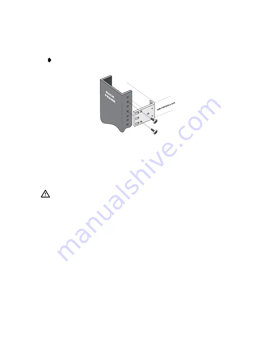
Note:

  If  mounting  the  assembly  in  a  23”  rack  refer  to  Figure  501-5  for  location  of

mounting  holes.

Figure 501-5. Front Mounting to 23î Rack

5. Position  the  Fan/Power  Supply  in  the  location  directly  above  the  installed  HWX

Equipment  Shelf  (if  front  mount,  place  the  bottom  of  the  unit  on  the  previously

mounted  rear  support  brackets  (step  4).  Align  the  mounting  holes  in  the  ears  with  the

applicable  holes  in  the  rack  or  cabinet  front  rails.

6. Use  appropriate  mounting  screws  to  secure  the  Fan/Power  supply  mounting  brackets

to  the  rack  or  cabinet  rails.  Tighten  the  mounting  screws  securely.

Warning:


Do  not  yet  attach  the  Fan/Power  Supply  AC  power  cord.

Stop! You have completed this procedure.

DLP-501

Page 4 of 4

Содержание Optiworx HW Series

Страница 1: ...IntegratedFan PowerSupply Procedures Manual 060914 000 Rev C...

Страница 2: ......

Страница 3: ...Procedures Manual for Optiworx HWX Integrated Fan Power Supply HW PSFAN 1 110 HW PSFAN 2 110 HW PSFAN 1 220...

Страница 4: ...P and SMART NETT are registered trade marks and Cable Network Manager CNM COR Convergence COR Connect FlexNode lumaCOR naviCOR Transfer Linearization and TL Technology are trademarks of C COR net Corp...

Страница 5: ...week on the C COR net Technical Support Hotline Technical Support Hotline 888 827 2267 Or call C COR net worldwide headquarters Monday through Friday 8 AM to 5 PM ET 5GMT and ask for the Applications...

Страница 6: ...bel Road State College PA 16801 7580 USA Providing Feedback on this Publication C COR net welcomes your suggestions and assistance in identifying any errors inaccuracies or misleading information Plea...

Страница 7: ...be useful to users of this one Title Description Part Number HWX Equipment Shelf and Power Supply Controller Installation and 060674 001 User Instruction Manual Contains information required for inst...

Страница 8: ...rostatic Discharge ESD protection practices Wear a grounded wrist strap when you touch a unit and when working on a unit always place it on an approved electrically grounded antistatic mat FCC Complia...

Страница 9: ...CTION 1 DESCRIPTION 1 GENERAL DESCRIPTION 1 1 2 PHYSICAL DESCRIPTION 1 1 3 FUNCTIONAL DESCRIPTION 1 3 4 SPECIFICATIONS 1 4 SECTION 2 INSTALLATION 1 GENERAL 2 1 2 HOW TO USE THIS SECTION 2 1 3 SAFETY I...

Страница 10: ...x FRONT MATTER 060914 000 Rev C This page deliberately blank...

Страница 11: ...8 VDC outputs are compatible with telco standard A BATT B BATT DC inputs Each Integrated Fan Power Supply s DC output provides 48 VDC at 300 watts Warning The Integrated Fan Power Supply dual output a...

Страница 12: ...anel Features LED AC Green when AC A and or B input is normal green 110 VAC version 90 130 VAC 220 VAC version 180 246VAC LED DC Green when DC A and or B output is normal green 48VDC 5 Rear Panel Feat...

Страница 13: ...vides input and output status signals to the front panel LEDs The green AC LEDs will illuminate when the AC input to the converters are at an acceptable level The green DC LEDs will illuminate when th...

Страница 14: ...PSFAN 2 110 25 15lb HW PSFAN 1 220 21 80lb Environmental Temperature Operating 0 C to 50 C 32 F to 122 F Storage 40 Cto 80 C 40 Fto 176 F Relative Humidity Operating 10 to 90 non condensing Storage 1...

Страница 15: ...nstructions for installing the HWX Integrated Fan Power Supply proceed as follows 1 Find the task to be performed in the Installation Task Index List IXL 001 2 Locate the procedure for the task Each p...

Страница 16: ...sembly and initial turn up and test Warning To prevent electrical shock never install electrical equipment in a wet location or during a lightning storm Caution HWX equipment is electrostatic discharg...

Страница 17: ...low Then Go To Pg INSTALL INTEGRATED FAN POWER SUPPLY NTP 002 2 4 Unpack Equipment and Inspect for Damage DLP 500 2 6 Installing the HWX Integrated Fan Power Supply DLP 501 2 7 Integrated Fan Power Su...

Страница 18: ...urces for one 1 HWX Equipment Shelf DO NOT attempt to connect this power supply to more than one equipment shelf Do Items Below in the Order Listed For Details Go To Pg DLP 500 2 6 DLP 501 2 7 DLP 502...

Страница 19: ...res for an Integrated Fan Power Supply assembly HW PSFAN x xxx consists of performing the following item Do Items Below in the Order Listed For Details Go To Pg 1 Connect and turn on AC power to the a...

Страница 20: ...s dents punctures etc that could indicate possible shipping damage If shipping damage is found refer to Contacting C COR net Technical Support on page v of this document for further instructions on ho...

Страница 21: ...nt electrical shock never install electrical equipment in a wet location or during a lightning storm Caution The dual supply version of the Integrated Fan Power Supply HW PSFAN 2 110 is designed to pr...

Страница 22: ...ets as required see Figure 501 1 and reattach them to the shelf in the new orientation reusing the original attaching screws Figure 501 1 Orienting Mounting Brackets For Integrated Fan Power Supply Mo...

Страница 23: ...o Rear Support Brackets 4 For front mounting only Position the rear support mounting brackets right and left on the rear rack frame in a manner that both provides side and rear support to the Fan Powe...

Страница 24: ...HWX Equipment Shelf if front mount place the bottom of the unit on the previously mounted rear support brackets step 4 Align the mounting holes in the ears with the applicable holes in the rack or ca...

Страница 25: ...river to match terminal block screws Ground wire 16AWG minimum stranded conductor length as required DC power wire 18 AWG minimum stranded conductor length as required Insulated fork spade crimp termi...

Страница 26: ...t supply HW PSFAN 1 xxx continue to step 6 If a redundant output supply HW PSFAN 2 110 go to step 7 6 Connect the Fan Power Supply terminal block Power Supply A 48V to either HWX Equipment Shelf s rea...

Страница 27: ...an Power Supply s V screw terminal to the HWX Equipment Shelf s screw terminal tighten screw terminal securely b Connect the second wire from the Fan Power Supply s V screw terminal to the HWX Equipme...

Страница 28: ...Fan Power Supply always follow Electrostatic Discharge ESD protection practices Wear a grounded wrist strap when you touch a unit Use antistatic packaging when transporting or storing units When worki...

Страница 29: ...ails all the LED indicators will be extinguished Go to step 4 2 Are the AC LEDs green and the DC LEDs extinguished If Yes go to step 3 If No continue to step 4 3 Using the digital voltmeter observing...

Страница 30: ...AC power module check that the AC power cord is connected to the IEC AC adapter and the male end of the power cord is connected to an active AC outlet If Yes continue to step 7 If No connect AC power...

Страница 31: ...type When complete repeat DLP 503 Note If application of power to the fan assembly continues to blow fuses suspect faulty Fan Power Supply assembly Disconnect wiring to the shelf remove and return the...

Страница 32: ...iangular symbol on the top of the fuse holder is pointing to the white line located at the bottom left side of the AC input power module as shown in the illustration For 220 VAC Model HW PSFAN 1 220 r...

Страница 33: ...is not present on DC A but is present on DC B suspect defective power supply A Although the assembly can still be used to power the HWX Equipment Shelf the redundancy feature no longer exists The unit...

Страница 34: ...PN 060914 000 Revision C October 2001 Page 2 20 2001 C COR net Corporation This page deliberately blank...

Страница 35: ......

Страница 36: ...6 5364255 Canadian Office 981 Mountview Court Oshawa Ontario L1K 2M1 Canada Tel 905 427 0366 Fax 905 428 0927 800 427 2559 Toll free for Canadian call only World Headquarters 60 Decibel Road State Col...

Отзывы: