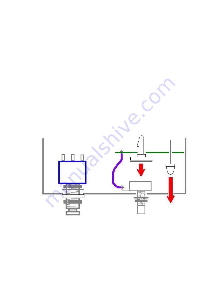
Do not clip the leads of the pots.
Solder Lugged Pots: Some kits may come with panel mounted pots with
solder lug termination. If you kit has these style pots, follow these steps
for mounting the PCB.
Step 1: Connect the pots to their eyelets on the PCB with hook up wire. Insert the wires
from the underside of the PCB and solder on the topside. Lug 1 of the A100k LEVEL
pot gots to the L1 eyelet. Lug 2 of the LEVEL pot goes to the L2 eyelet. Lug 3 of the
LEVEL pot goes to the L3 eyelet. Lug 1 of the B1k ATACK pot goes to the A1 eyelet.
Lug 2 of the ATTACK pot goes to the A2 eyelet. Lug 3 of the ATTACK pot goes to the
A3 eyelet.
Step 2: Install the self-adhesive nylon standoffs from the underside of the PCB into the
large mounting eyelets, but do not remove the paper backings yet.
Step 3: Install the LED into the underside of the PCB, but DO NOT SOLDER IT YET!
The longer lead goes in the round pad and the shorter lead goes in the square pad. Not
that's not a typo. Yes that is correct. Longer lead in the round pad. Shorter lead in the
square pad. Bend the leads of the LED outward on the topside of the PCB so that it does
not fall out when you flip it over.
Step 4: Now remove the paper backings from the standoffs and adhere them to the backs
of the pots. It's a good idea to clean the backs of your pots with some rubbing alcohol
first.
Step 5: Grab the LED by the leads that are sticking out of the topside of the PCB and
guide it into place. Solder it from the topside and clip the excess leads.


