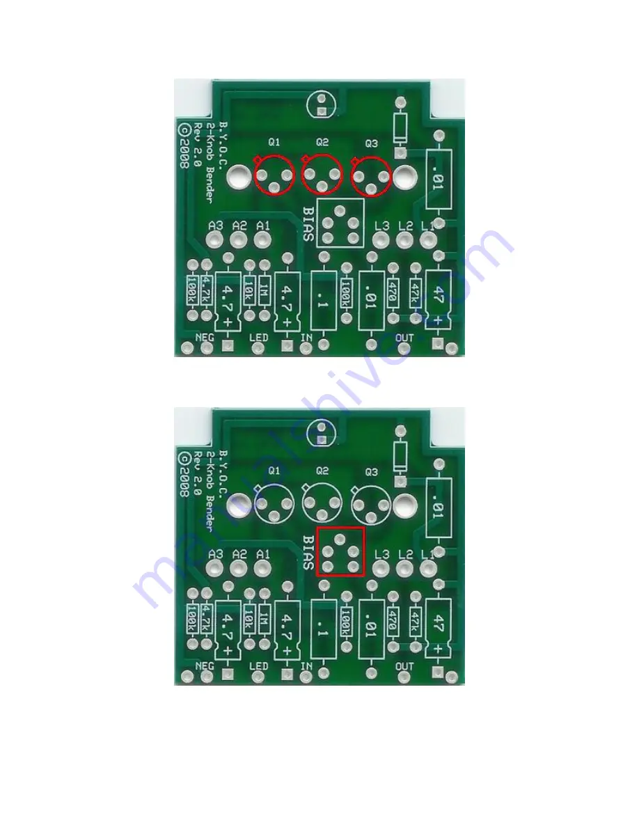
Step 3: Add the transistor sockets. DO NOT SOLDER THE TRANSISTORS TO THE
SOCKETS!!!!!!!!!!! Only solder the sockets to the PCB. Make sure to match the tab of
the socket to the tab of the PCB layout.
Step 4: Add the bias trimpot. Do not be confused by the fact that the PCB has holes for 5
legs and the actual trimpot only has 3. This is so that the PCB can accept a variety of
trimpots. There should be only one way in which your trimpot will fit the PCB without
having to bend any of the legs.


