


Page 10
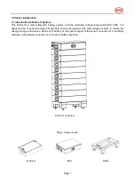
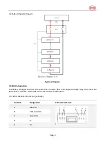
3.5.2 BCU interface introduction [Right side]
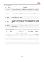
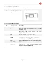
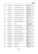
3.5.3 BCU Functional Interfaces Definition
No.
Interface Name
Description
1
P+
The system positive terminal, connected to the inverter positive
terminal for battery
2
P-
The system negative terminal, connected to the inverter
negative terminal for battery
3
GND
Grounding terminal, connected to the ground.
4
Ethernet
Connected to the Ethernet, to complete the functions of
communication and remote program update.
5
Inverter
communication
Containing RS485, CAN, and enable signals, outputting 13V
power.
6
System switch
The main switch of system, which can be operated manually
and has the short circuit protection fun.
Position
Designation
Right side terminals
A
Air switch waterproof cover
B
System Air switch


