Part 1
Before Installation
6
www.plusdeck.com
●
7
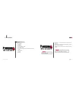
Check all following components are in the box. If you find any component missing or
damaged, contact the distributor or manufacturer.
1. Plusdeck2c main body
2. 20 pin cable
3. Connection card
4. Serial cable(RS232C cable)
5. Stereo cable 3 EA
6. Installation CD
7. User manual
8. Fixing screws
■
A crossed screwdriver is needed to install the Plusdeck2c.
■
If you move it to a different computer, all other components should follow it.
Plusdeck2c components
4
❶
Plusdeck2c main body
❸
Connection card
❺
Stereo Cable 3 EA
❼
User manual
❽
Fixing screws
❻
Software CD
❹
Serial cable (RS232C cable)
❷
20 pin cable
green
blue
pink
Plusdeck2c Specification
5
Electromagnetic Wave Compliances
6
E-H900-01-5845(B)
•
Size (W
×
H
×
D): 145
×
40
×
215mm
•
Tape speed: 4.75Cm/sec
•
Wow & Flutter: 0.09%(WRMS)
•
Frequency response: 20 ~ 18,000Hz
•
Separation: 40dB
•
Signal to Noise Ratio : 55dB
•
Power: DC12V
FCC Information
This is device complies with Part 15 of the FCC Results.
Operation is subject to the Following two conditions:
(1) This Device may not cause harmful interface, and
(2) This Device must accept any interference received,
including interference that may cause undesired
operation.
Note
: This equipment has been tested and found to
comply with the limits for CLASS B digital device,
pursuant to Part 15 of FCC Rules. These limits are
designed to provide reasonable protection against harmful
interference when the equipment is operated in a
commercial environment.This equipment generates, uses
and can radiate radio frequency energy and, if not installed
and used in accordance with the instructions, may cause
harmful interference to radiocommunications. However,
there is no guarantee that interference will not occur in a
particular installation. If this equipment does cause
harmful interference to radio or television reception, which
can be determined by turning the equipment off and on,
the user is encouraged to try correct the interference by
one or more of the following measures:
1.1.Reorient or relocate the receiving antenna.
1.2.Increase the separation between the equipment
and receiver.
1.3.Connect the equipment into an outlet on a circuit
different from that to which receiver is connected.
1.4.Consult the dealer or experienced radio/TV
technician for help.
WARNING
Changes or modifications not expressly approved by the
manufacturer could void the user's authority to operate
the equipment.
FCC ID : R4EPlusdeck2c-1


