Page 14
BSS-Streaming Service
BSS-Case
Installation of the Lilliput A11-10,1“ Monitor
Only relevant for BSS-Case version “Pure”
Required tools: Allen key size 3
he cables for installing the Lilliput A11-10.1” screen are labeled and
must be plugged in according to the label on the screen. See the oper‐
ating instruction of the monitor.
Note: The cable lengths and wiring are designed exclusively for this monitor
and may only be used with it. Contact our service team if you want to install a
different monitor.
Before plugging in, check the lengths of the cables. These must be posi‐
tioned properly when plugged in, without being under tension.
Avoid kinks and tight bends.
Check that no cables are pinched or kinked or are placed under tension
when the cover is closed
• Cable label “HDMI in” - plug
into the monitor to “HDMI
in”
• Cable label “HDMI out” -
plug into the monitor to
“HDMI out”
• Headphone connection -
plug the angled plug on the
monitor into the “Earphone
Jack” socket, make sure that
the angled plug points to
the right when plugging in.
• Plug 12V DC, plug this into the 12V input of the monitor.
• Before attaching the monitor, check that all cables are properly
seated.
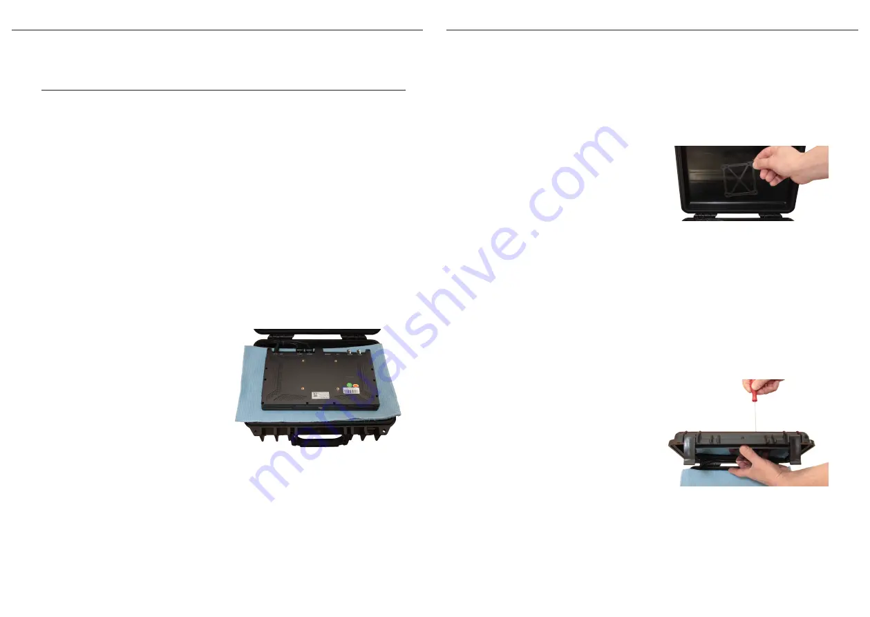
(Image 8) Place the monitor on a soft cloth
Page 15
Screw the monitor on
Tip: To avoid scratches, place a soft cloth on the cover plate of the BSS case,
then you can place the monitor there. (Image 8)
Have the pan head screws
M4x12 ready. Insert these from
the outside in through the cor‐
responding holes in the cover
of the case. Place the mounting
plate on the four screws. Posi‐
tion the monitor with its fas‐
tening threads congruently on
the corresponding screws in the case lid.
Tip: Only hold the monitor by the frame to avoid fingerprints on the display.
Find the first of the four fastening threads with slight movements. To do
this, hold the corresponding screw against it from the outside with the
Allen key.
Tighten all four screws from the outside, keeping them loose at first un‐
til they are all screwed on. Carefully retighten the screws. Max. tighten‐
ing torque 0.4 Nm (!) (Im‐
age 10)
After you have installed the
ATEM Mini according to the in‐
structions, test the picture and
sound of the monitor. Refer to
the monitor’s operating in‐
structions for more informa‐
tion.
(Image 9) Position the monitor bracket
(Image 10) Screw on the monitor
Operating instruction EN
DOC-000001


