


66
d. Shall have tool--less connection terminal access.
e. Shall have a recessed momentary switch for testing and resetting the detector.
f. Controller shall include:
(1.) One set of normally open alarm initiation contacts for connection to an initiating device circuit on a fire
alarm control panel.
(2.) Two Form--C auxiliary alarm relays for interface with rooftop unit or other equipment.
(3.) One Form--C supervision (trouble) relay to control the operation of the Trouble LED on a remote test/reset
station.
(4.) Capable of direct connection to two individual detector modules.
(5.) Can be wired to up to 14 other duct smoke detectors for multiple fan shutdown applications
19. Winter start kit
a. Shall contain a bypass device around the low pressure switch.
b. Shall be required when mechanical cooling is required down to 25
_
F (--4
_
C).
c. Shall not be required to operate on an economizer when below an outdoor ambient of 40
_
F (4
_
C).
20. Time Guard
a. Shall prevent compressor short cycling by providing a 5--minute delay (
±
2 minutes) before restarting a com-
pressor after shutdown for any reason.
b. One device shall be required per compressor.
21. Hinged Access Panels
a. Shall provide easy access through integrated quarter turn latches.
b. Shall be on major panels of – filter, control box, fan motor and compressor
581J
Содержание 581J
Страница 51: ...51 TYPICAL WIRING DIAGRAMS C08518 Fig 15 1 Stage Cooling Typical Power Diagram 581J ...
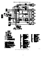
Страница 52: ...52 TYPICAL WIRING DIAGRAMS cont C08577 Fig 16 2 Stage Cooling Typical Power Diagram 581J ...
Страница 53: ...53 C08524 Fig 17 1 Stage Typical Wiring Diagram 581J ...
Страница 54: ...54 C08578 Fig 18 2 Stage Typical Wiring Diagram 581J ...


