Bandit
72
Copyright 6/12
MODEL 200 UC
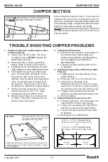
FIGURE 1
Fill working edge with hard surface weld
as flat to anvil surface as possible. Use a
non‑weldable bar stock (Brass)
BRASS
BAR
ANVIL
REMOVE BRASS BAR AFTER BUILDING UP AREA WITH
HARD SURFACE WELD AND SQUARE WORKING CORNER
WITH GRINDER.
TROUBLE SHOOTING CHIPPER PROBLEMS
Knives should be replaced in sets. These sets are
determined by the amount of resharpening done to
the knives. It should be reinstalled with another knife
of comparable usage. It helps to keep the disc/drum
balanced, and it helps maintain chip quality.
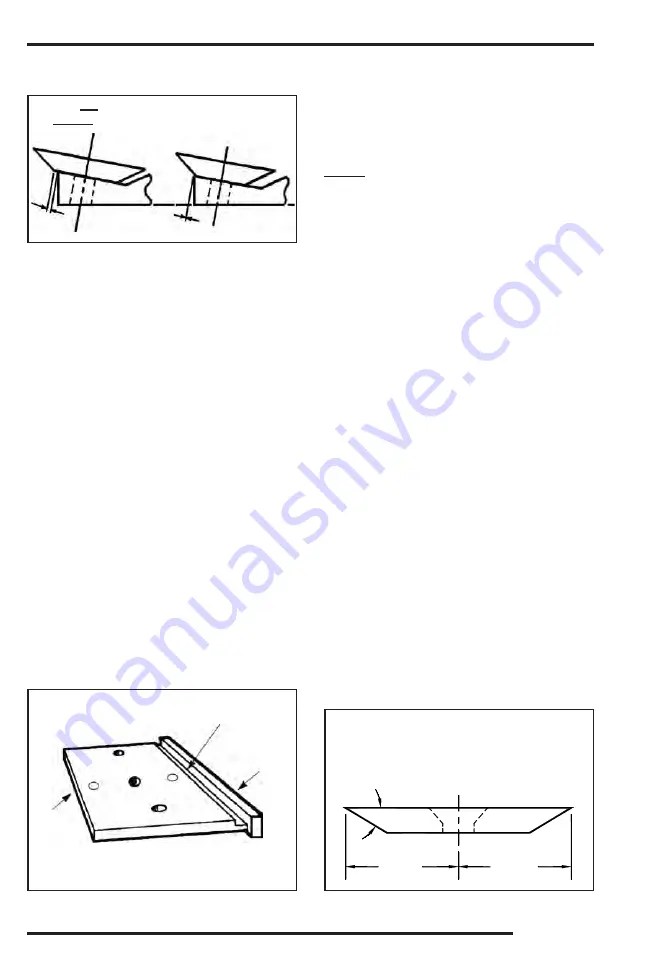
NEVER allow these knives to wear beyond absolute
specified minimum distance from the center line of
bolt (see below).
YES
NO
UNDER
NO
SITUATION IS HEAL OF KNIFE TO
BE
INSIDE
EDGE OF MILLED POCKET!
2. Chipper Knife Hits Anvil.
A. Check the anvil clearance at both sides of
the knife by using a feeler gauge, the
clearance should be the specified distance
from the highest knife (SEE ANVIL
ADJUSTMENT).
B. Check the chipper bearing shaft lock nut
for
tightness.
3. Discharge Plugs or Does Not Throw Chips
Properly.
A. Lugging engine on large material ‑ keep
engine RPM up.
B. Knives are dull or worn to minimum size.
C. Obstruction in discharge chute.
Patches welded into the chute can cause
obstruction of chip flow. Anything causing
an obstruction will cause the chute to plug.
D. Chipping rotting material that has little
substance can also plug the discharge chute.
E. Worn fan blades.
4. Chipper Bearings Running Too Hot.
A. Improper lubrication ‑ purge bearings once
a day with EP‑2 Lithium type grease.
B. Chipper disc operating at too high RPM’s.
DO NOT exceed recommended RPM’s.
C. Check the chipper bearing locking collars
for
tightness.
D. Bearings worn out (REPLACE).
1. Chipper makes poor quality chips or does
not feed properly.
A. Knives have lost their edge. File, grind
or replace knives.
DO NOT
operate the
Bandit with dull knives.
B. Knife anvil worn or needs adjustment.
Rotate, repair or replace (see Figure 1).
C. Feedwheel(s) are not operating correctly.
(SEE HYDRAULIC TROUBLE SHOOTING).
D. The throat/base opening is a high‑wear
area. The feed plate anvil takes much of
this wear but other areas wear as well.
Attention must be paid to any areas where
outer, noncutting edges of chipper knife
are exposed. These areas must be built
up with weld to maintain the original integrity.
E. Knives are at the wrong angle. Knives
must be ground at a 30° to 31° angle.
F. Feedwheel teeth worn (REPLACE).
G. Material being chipped is very small, dry
or rotting. This type of material does not
produce good chip quality.
CHIPPER SECTION
CHIPPER SECTION
1 13/16”
(46 mm)
1 13/16”
(46 mm)
30°
3/8” x 4” x 7 1/4” Chipper Knives
(9.5 mm x 101.6 mm x 184.2 mm)
&
1/2” x 4” x 7 1/4” Chipper Knives
(12.7 mm x 101.6 mm x 184.2 mm)
Содержание 200 UC
Страница 17: ......
Страница 35: ...Bandit 19 Copyright 6 12 MODEL 200 UC DECALS ...
Страница 36: ...Bandit 20 Copyright 6 12 MODEL 200 UC DECALS ...
Страница 69: ...Bandit 53 Copyright 6 12 MODEL 200 UC HYDRAULIC SECTION HYDRAULIC SECTION ...
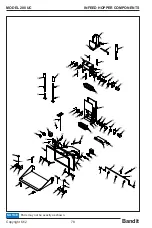
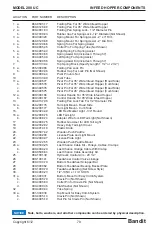
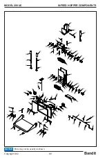
Страница 94: ...Bandit 78 Copyright 6 12 MODEL 200 UC INFEED HOPPER COMPONENTS Parts may not be exactly as shown NOTICE ...
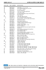
Страница 96: ...Bandit 80 Copyright 6 12 MODEL 200 UC INFEED HOPPER COMPONENTS Parts may not be exactly as shown NOTICE ...
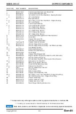
Страница 98: ...Bandit 82 Copyright 6 12 MODEL 200 UC CHIPPER COMPONENTS Parts may not be exactly as shown NOTICE ...
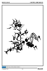
Страница 100: ...Bandit 84 Copyright 6 12 MODEL 200 UC CHIPPER COMPONENTS Parts may not be exactly as shown NOTICE ...
Страница 122: ...Bandit 106 Copyright 6 12 MODEL 200 UC Parts may not be exactly as shown NOTICE FUEL HYDRAULIC TANK COMPONENTS ...
Страница 126: ...Bandit 110 Copyright 6 12 MODEL 200 UC SERVICE RECORD SERVICE RECORD DATE DESCRIPTION AMOUNT ...


