background image

Bandit

87

Copyright 6/12

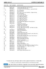
MODEL 200 UC

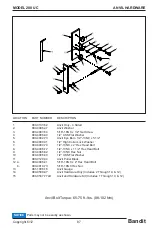
LOCATION 

PART NUMBER 

DESCRIPTION

1.   

980‑0133‑52 

Anvil Only ‑ 4 Sided

2.   

900‑4908‑47 

Anvil Washer

3.   

900‑4903‑54 

5/16”‑18NC x 1/2” Set Screw

4.   

900‑4906‑90 

1/2” USS Flat Washer

5.   

900‑4902‑73 

Anvil Eye Bolt ‑ 1/2”‑13NC x 5 1/2”

6.   

900‑4900‑31 

1/2” High Collar Lock Washer

7.   

900‑4900‑74 

1/2”‑13NC x 2” Hex Head Bolt

8.   

900‑4906‑72 

1/2”‑13NC x 1 1/2” Hex Head Bolt

9.   

900‑4906‑82 

1/2”‑13NC Hex Nut

10.  

900‑4906‑90 

1/2” USS Flat Washer

11.  

980‑0129‑34 

Anvil Puller Block

12  a. 

900‑4906‑41 

5/16”‑18NC x 2” Hex Head Bolt


b. 

900‑4910‑73 

5/16”‑18NC Hex Nut

13.  

981‑1006‑16 

Anvil Gauge

14.  

980‑0508‑97 

Anvil Hardware Only (Includes 2 Through 10, & 12)

15.  

980‑0507‑77LD 

Anvil and Hardware Kit (Includes 1 Through 10, & 12)

Anvil Bolt Torque: 65‑75 ft.‑lbs. (88‑102 Nm)

ANVIL HARDWARE

Parts may not be exactly as shown.

NOTICE

Содержание 200 UC

Страница 1: ...ch Make __________________ Model ___________ S N ________ ATTENTION Dependingonwhat replacement parts you are ordering we will need the following information CHIPPER COMPONENTS Serial Number Model Number of Chipper ENGINE COMPONENTS Brand Engine Serial Number Engine Model Number CLUTCH COMPONENTS Brand Clutch Serial Number Clutch Model Number Copyright 6 12 MANUFACTURED BY BANDIT INDUSTRIES INC 67...

Страница 2: ...ngs ca gov diesel Respirar gases de escape de motores diesel le expone a quÍmicos conocidos por el estado de California como causales de cáncer y defectos congénitos u otros daños reproductivos Para mayor informaciÓn visite www P65warnings ca gov diesel Siempre encienda y opere el motor en áreas bien ventiladas Si está en un área cerrada ventile escape hacia el exterior No modifique ni altere el si...

Страница 3: ...Bandit Industries Inc Safety Booklet D A N G E R ACCIDENTS INVOLVING BRUSH CHIPPERS CAN AND SHOULD BE PREVENTED Operator training and enforcement of safety policies are ESSENTIAL ...

Страница 4: ...r 989 561 2270 Most if not all chipper related accidents are caused by operator negligence A lack of proper and ongoing training and lack of enforcement of safety policies significantly increase the opportunity for operator error Many companies involved in tree care or tree maintenance have weekly meetings to review potential hazards and discuss how accidents can be avoided These meetings are a be...

Страница 5: ...r Brush chippers are designed to be operated with hands placing the material into the chipper NOT FEET If the operator kicks the material that has become lodged or is not going into the feedwheels he or she is placing themselves in extreme danger If the wood does free up and goes into the feedwheels the operator can be thrown off balance NEVER KICK OR PLACE A FOOT IN THE CHIPPER INFEED HOPPER Use ...

Страница 6: ...from your local Bandit dealer SAFETY FEATURE WOODEN PUSH PADDLE MOUNT Update Kit UK 1008 WOODEN PUSH PADDLE AND MOUNT 626 0000 52 14 Wide Paddle 980 0507 42 19 Wide Paddle 981 1005 30 22 Wide Paddle 980 200147 34 Wide Paddle SAFETY FEATURE WELD ON INFEED PAN EXTENSION You must supply the chipper model number and chipper serial number when ordering to ensure an accurate fit of the weld on pan or pa...

Страница 7: ... padlocked SAFETY FEATURE SPRING LOCK FOR HOOD PIN Update Kit UK 1009 SPRING LOCK FOR HOOD PIN Since September 1998 mechanical feed hand fed Bandit Chippers have been built with a plug in device on the chipper hood that disables the engine if the hood pin is not properly in place holding the chipper hood in the closed position Correctly installed and maintained the engine will not start or it will...

Страница 8: ...ctric parts The system typically consists of two simple cables hanging inside the infeed hopper and in front of the feedwheels approximately halfway between the entrance of the infeed hopper and the feedwheels If an operator incorrectly finds themselves past the feed control bar and inside the infeed hopper he she has a cable to reverse stop feedwheels and wood flow The Last Chance Stop is Not ins...

Страница 9: ...the chipper must be familiar understand and follow instructions on the decals Decals are available in a variety of languages via Bandit dealers or factory Correct Installation and Care of Decals 1 You should use soap and water to keep your decals clean Never use mineral spirits or any other abrasive cleaners 2 Replace immediately any missing or damaged decals The location the decal is going to be ...

Страница 10: ...peration In the long run sharp knives can save you money The chipper knives must be of good quality and the correct design for that model chipper The knives must be properly hardened at the edge annealed at the bolt holes and the correct metallurgical composition Improper knives may break and cause a dangerous and costly accident Use only factory approved knives and mounting hardware from Bandit I...

Страница 11: ...ipper disc drum by hand Always use a pry bar or wood bar This will prevent the person turning the disc drum from being injured should the disc drum break loose 8 Reinstall the discharge chute mount securely and point it in a safe direction away from anything 9 Never leave the chipper hood open and try to start the engine in order to engage the chipper disc drum to blow chips out of the housing thi...

Страница 12: ...uent reminder as to the proper safe operation of any piece of equipment especially a chipper that is designed to quickly break down material much tougher than human flesh Please meet with your employees and have them read this Safety Booklet Ask them what they think about the dangers we have discussed Ask them if they have been guilty of some of the unsafe practices addressed in this bulletin Lect...

Страница 13: ...n an unsafe manner Customer understands to never attempt to override any safety devices or guards 7 ____ Customer has been instructed and understands to always remove the ignition key and completely disconnect battery from cables wait for the chipper disc drum to come to a complete stop and to install the disc drum lock before performing any type of maintenance on the machine Allow all the time ne...

Страница 14: ...t as ordered ________________________________________________ 5 Did all welds appear to be high quality ______________________________________________ 6 Was the overall machine to your liking ______________________________________________ 7 What problems have you experienced ______________________________________________ 8 Have any components regularly loosened that caused problems _______________...

Страница 15: ...CHIPPER SECTION 72 LUBRICATION COOLANT 75 ELECTRICAL SECTION 76 REPLACEMENT PARTS SECTION 77 INFEED HOPPER COMPONENTS 78 CHIPPER COMPONENTS 82 CHIPPER KNIFE HARDWARE 86 ANVIL HARDWARE 87 DISCHARGE COMPONENTS 88 HYDRAULIC COMPONENTS 93 FRAME ACCESSORY COMPONENTS 102 FUEL HYDRAULIC TANK COMPONENTS 106 OPTIONAL COMPONENTS 108 SERVICE RECORD 110 ANY PART PORTION DESIGN NUMBER SPECIFICATION AND OR DIME...

Страница 16: ...sponsibility to provide and follow a regularly scheduled preventative maintenance and repair program on the product using only factory approved replacement parts Any unapproved repairs or modifications may not only damage the machine and its performance but could result in severe personal injury Unapproved repairs or modifications will void warranty and eliminate manufacturer of any liability clai...

Страница 17: ......

Страница 18: ...CHIPPER SERIAL NUMBER AND OR WORK ORDER NUMBER LOCATIONS 1 Beltshield 2 W O on top of tongue The engine information is located on the engine block The clutch information is located on the clutch plate if equipped SERIAL NUMBER LOCATIONS NOTICE 2 1 ...

Страница 19: ...ancer birth defects and other reproductive harm SAFETY PROCEDURES The words Danger Warning Caution and Notice are used on the safety decals and throughout this manual to make you aware of the safety procedures These procedures are very important read and obey them YOUR SAFETY IS VERY IMPORTANT TO US This machine is equipped with safety decals guards and designs for your protection Don t ever take ...

Страница 20: ...ne to possibly lug down If it starts lugging down stop the feedwheel s by pushing the hydraulic control bar to off and let the engine recover to full speed If the machine is equipped with Autofeed and it is functioning properly the feed system will automatically stop to let the engine recover This will help stop the machine from plugging the discharge chute Pay attention to the direction of the di...

Страница 21: ...al DO NOT pile vines or vine like material in front of the infeed hopper which may cause you to trip or fall DO NOT allow vines or limbs to become entangled with you or your clothing DO cut vine like material into 4 to 5 foot 1 2 to 1 5 meter length s away from the chipper area DO stop the feed system before feeding the cut vine like material into the infeed hopper DO use a wooden pusher paddle wh...

Страница 22: ...in gear until it locks into position securely After engagement raise engine RPM to full throttle Engaging and disengaging the clutch at high engine RPM will quickly and excessively wear out clutch plates as well as bearings Refer to clutch manufacturer s manual for proper service and operation Do not work inside the mouth of the chipper or around the feedwheel s until you have installed the yoke l...

Страница 23: ...ith your fuel or fuel system supplier to ensure the delivery system is in compliance with fueling standards for proper grounding and bonding practices WARNING If the discharge or hood need to be removed always use some sort of mechanical device like an overhead hoist loader lift truck etc that is rated for lifting that component Follow all OSHA instructions for lifting Before opening or closing th...

Страница 24: ... line The knives on the spinning disc drum can grab and pull in the winch line at a high rate of speed resulting in serious injury or death to workers nearby DANGER The winch line is under tension at times and could suddenly release snapping back into the operator causing serious injury or death DANGER Never operate the hydraulic winch with the wood chipper detached from the towing vehicle The loa...

Страница 25: ...e chipper with the bottom clean out door in the open position because it subjects the door to physical abuse and damage during transportation This can damage the hinge and prevent the door from being properly closed during operation Once the bottom clean out door has been opened to perform maintenance or prevent debris from damaging the chipper the door should always be closed before continuing op...

Страница 26: ...eeding into the chipper Never attach winch line to an installed choker if other limbs are feeding into the machine Brush can snag winch line or climbers ropes Knives can grab and pull in line and anything attached to it at a high rate of speed If you are in between the chipper and the winch line that is caught in the knives the winch line will be pulled in at a very rapid speed and you will not ha...

Страница 27: ...he feedwheel teeth from slipping on the material DO NOT OVERTIGHTEN This will overwork the hydraulic system and make it difficult to feed larger material Always start the larger end base end of the log tree or branch into the feedwheel s first Keep the engine R P M s at full throttle whether you are chipping brush or round wood Lower R P M s will cause weak throwing power and can cause plugging in...

Страница 28: ...l system NEVER sit stand lay climb or ride anywhere on this machine while it is running operating or in transit You will be injured Use EXTREME CAUTION when traveling over non level surface This machine can tip over or tip backwards on non level surface You will cause engine damage machine damage and possible personal injury Any increase from the specified maximum operating angles may cause loss o...

Страница 29: ...bs 1950 to 2130 kg Approximate weights depending on engine and equipment options Overall Dimension Model 200 UC Height 8 2 4 m Length 16 8 5 1 m Width 5 10 1 8 m Fuel Tank Capacity 24 1 2 Gallons 92 Liters Hydraulic Tank Capacity 12 Gallons 45 Liters Approximate dimension depending on equipment options EQUIPMENT SPECIFICATIONS EQUIPMENT SPECIFICATIONS HEIGHT WIDTH LENGTH ...

Страница 30: ...UC Decal locations may vary these are general locations DECALS DECAL LOCATIONS 35 1 3 43 8 12 41 45 46 30 44 34 35 29 28 2 20 7 9 31 2 16 24 25 26 27 33 36 39 12 47 4 5 18 20 22 23 48 37 38 40 15 2 20 19 21 2 16 14 6 10 13 20 32 11 17 42 ...

Страница 31: ... Coupler Guard 20 INST 12 Grease Daily Arrow 21 SPINST 13 Push To Reverse 22 INST 14 Articulating Tongue Out In 23 INST 15 Flipper Down Up 24 INST 16 Grease Weekly Arrow 25 INST 39 Oil Daily Arrow 26 INST 44 California Proposition 65 27 INST 46 Autofeed Basic Info 28 INST 48 Disc Drum Lock Tube 29 INST 49 Disc Drum Lock Pin 30 INST 53 Hydraulic Oil Hydrex XV 31 INST 76 Yoke Lift Down Up 32 INST 95...

Страница 32: ...UC Decal locations may vary these are general locations DECALS DECAL LOCATIONS 35 1 3 43 8 12 41 45 46 30 44 34 35 29 28 2 20 7 9 31 2 16 24 25 26 27 33 36 39 12 47 4 5 18 20 22 23 48 37 38 40 15 2 20 19 21 2 16 14 6 10 13 20 32 11 17 42 ...

Страница 33: ...Diesel Fuel Only 46 SPW 03 Gasoline Fuel Only 47 SPW 04 Frozen Battery Can Explode 48 SPW 08 Wear Personal Protection 49 900 8900 30 Basic Safety Decal Kit Options may require additional decals 50 900 8901 91 Bandit Model 200 UC Logo Decal Kit Some decals are for optional equipment Decal locations may vary these are general locations If any decals become damaged replace immediately DECALS DECAL LO...

Страница 34: ...n place and in good condition on your machine Please follow the care and instructions given below 1 You should use soap and water to keep your decals clean Never use mineral spirits or any other abrasive cleaners 2 Replace immediately any missing or damaged decals The location the decal is going to be applied to must be clean and dry and at least 40 F 5 C before applying decal 3 When the need aris...

Страница 35: ...Bandit 19 Copyright 6 12 MODEL 200 UC DECALS ...

Страница 36: ...Bandit 20 Copyright 6 12 MODEL 200 UC DECALS ...

Страница 37: ...sume forward travel Due to required components and equipment options a machine may have various types or brands of autofeed systems Each chipper is shipped with the original manufacturer s manual for the autofeed system it is equipped with For the approximate autofeed settings on all optional autofeed systems refer to page 24 of the chipper manual For part numbers on the hydraulic portion of the a...

Страница 38: ... or on the newer machines it will have a connector with a light screwed to it When the solenoid is activated indicated by the light in the connector the feedwheel s are reversed by the autofeed plus system See Figure 3 Normally seen on bigger machines such as 280 1850 1890 1990 2090 etc and special options This will normally be located on the infeed hopper of the machine It can recognized by a val...

Страница 39: ... or out of adjustment throttle cable This would not let engine reach full RPM Check HI RPM setting on gauge to make sure it is not set too close to full RPM of engine HI setting should be 150 to 200 RPM below full engine RPM Lightly tap on dump block to free up Take cartridge out and clean free of debris Replace solenoid and or cartridge Check and readjust per manual specifications Consult local d...

Страница 40: ...rong Sticking reverse valve Type settings programmed wrong Reset backup time Normal setting is 3 seconds Check solenoid operation Override cartridge manually by sticking a small allen wrench in the end of the solenoid Replace solenoid and or cartridge Reprogram or consult local dealer or Bandit Ind Some Current Engine Types John Deere 4024 80 Hp CAT C3 4T 84 5 Hp CAT C4 4T 97 Hp Cummins B3 3 74 Hp...

Страница 41: ...ORT BY HAND OR WITH A PULL ON LAST CHANCE CABLES LUBRICATE PIVOT POINTS OF FEED CONTROL HANDLE WEEKLY ADJUSTING TENSION FOR CONTROL HANDLE PIVOT AND LAST CHANCE CABLE PULL CORRECT OPERATION OF FEED CONTROL HANDLE PUSH TO REVERSE FEEDING FEEDING OFF FOR ALL CHIPPERS DESIGNED TO BE HAND FED IF YOU ARE IN THE AREA OF THE INFEED HOPPER ALWAYS BE PREPARED TO OPERATE AND WITHIN EASY REACH OF THE FEED CO...

Страница 42: ...ar 10 Wooden Push Paddle 11 Hydraulic Control Valves 12 Yoke Lift Cylinder Optional 13 Swivel Discharge 14 Adjustable Height Discharge Optional 15 Discharge Chute 16 Discharge Flipper Adjuster 17 Autofeed Controls Optional 18 Engine Controls Adjusters 19 Electric Engine Throttle Adjuster if equipped 20 Bandit Lever Throttle Adjuster if equipped Basic Location of Controls and Components CONTROLS CO...

Страница 43: ...rap door can be opened DANGER Remove transport bolt and or lock pin BEFORE operating this function Discharge Swivel Control Optional The discharge swivel control operates the discharge rotate To make the discharge swivel to the right push the discharge swivel control handle down towards the ground To make the discharge swivel to the left pull the discharge swivel control handle up away from the gr...

Страница 44: ...unning This is for safety purposes to ensure that the hood pin is not removed and the chipper hood is not opened while the engine is running The chipper hood engine disable plug is wired to shut down the chipper engine When the disable plug is pulled out of the electric socket the electric circuit is broken disabling the engine The engine disable plug has a circuit fuse If the engine will not star...

Страница 45: ...when the hood pin is properly installed in place holding the chipper hood in the closed position see figure 1 With the chipper hood shut and hood pin in place the spring lock helps keep the hood pin from sliding out or from being removed if the chipper disc is turning There is a shaft cam block installed on the chipper shaft which will not allow the spring lock to be pulled down if the chipper dis...

Страница 46: ...have a choke adjustment pull the choke lever out to choke the engine Push the choke lever in for normal engine operations 5 Throttle Adjustment if equipped Some engines may have a knob or a handle for the throttle adjustment Typically you would pull the knob out or turn the handle to increase the engine R P M s To decrease you would push in the knob or turn the handle the opposite way 6 Bandit Lev...

Страница 47: ...ure they are operating correctly 14 Do not transport unless discharge is clamped pinned and bolted securely into place in the transport position pointed over the tongue 15 If machine is equipped with a chip box lock the turntable in the transport position 16 Check tires for correct pressure cuts or damaged rims 17 Check lug nuts and retorque if necessary Check new units before operation check agai...

Страница 48: ...r bed there should be about 15 of the total trailer package weight on the tongue or hitch 6 The loading ramps or loading gate of the trailer must be constructed to withstand the weight and forces involved in loading and unloading the machine 1 Make sure the trailer and towing vehicle are parked on a flat surface They must be stable on the surface with the brakes locked and or the wheels chocked to...

Страница 49: ...g or damaged decals and or engine gauges 2 Check all safety equipment Check for proper operation Repair or replace as needed With everything shut down and stopped insure last chance cables freely operate feed control valve 3 Check entire machine for loose bolts nuts parts or components Check entire machine for any loose parts or components Check for loose nuts or bolts Torque tighten or replace an...

Страница 50: ...efully manually with a pry bar or wood bar turn the chipper disc drum a full revolution This is to ensure the anvil and knives have proper clearance If the chipper disc drum is jammed with debris or frozen in place DO NOT attempt to start the engine and engage clutch until the chipper disc drum rotates freely 9 Check the condition of the fan blades knives anvil and attaching hardware Grind file or...

Страница 51: ... working edge Refer to pages 44 45 for the exact checking of anvil clearance procedure 2 Check alternator and fan belts on engine Inspect belt condition and replace as needed As applicable adjust and maintain per the engine manufacturer s manual 3 Check spring tension on feed system Do not over tighten Keep tight for small diameter material and progressively looser for larger diameter material See...

Страница 52: ... manufacturer s instructions 9 Check and adjust brakes Check and adjust brakes as needed per axle MFG manual 10 Check discharge chain tension if equipped Check tension on hydraulic or hand crank swivel discharge chain drive and tighten as necessary Chain tension is 1 4 6 mm per foot 0 3 m of center distance between sprockets NOT to exceed a 1 2 13 mm of deflection Do not overtighten which may resu...

Страница 53: ...gine Sheave Bushing SF 3 8 16 NC 30 41 Engine Sheave Bushing 2517 1 2 13 NC 60 81 Chipper Sheave Bushing E 1 2 13 NC 60 81 Chipper Sheave Bushing F 9 16 12 NC 75 102 Autofeed Cartridge Nut 4 6 5 8 Autofeed Plus Solenoid Retainer Nut 4 6 5 8 Hitch Mount Bolts 5 8 11 NC 220 298 MAINTENANCE SECTION 5 6 Lug Hubs 1 2 20 Studs 90 120 ft lbs Torque 122 163 Nm 8 Lug Hubs 1 2 20 Studs 90 120 ft lbs Torque ...

Страница 54: ...correctly 12 Grease chipper bearings purge and feedwheel bearings 1 shot daily 13 Check and adjust belt tension on chipper and hydraulic pump belt drives or replace 14 Check hydraulic pump and motor shafts for fit and tightness 15 Check and always maintain hydraulic level at 7 8 full 16 Check all hoses fittings lines and tanks for damage and fluid leaks 17 Check hydraulic control valves and ensure...

Страница 55: ...r wear 3 Inspect feedwheel motor connection 4 Check feedwheel teeth for sharpness 5 Check retighten all bearing and chipper sheave bolts 6 Check hydraulic function pressures Set to specified PSI bar 7 Check and fill tires to rated pressure 8 Check and grease or oil wheel bearings follow axle MFG instructions 9 Check and adjust brakes follow axle MFG instructions 10 Check and adjust discharge chain...

Страница 56: ...CK DESCRIPTION DAY WEEK MONTH PROCEDURE 1 Disc Drum Bearings X Purge bearings daily wipe off excess 2 Feedwheel Bearings X 1 shot of grease wipe off excess 3 Hood Hinge X 1 to 2 shots of grease wipe off excess 4 Steel Friction Areas pivoting X Lubricate i e control handle discharge hinged sliding rolling flipper folding pan etc 5 Chain Driven Components X Dry lube Swivel discharge chain driven fee...

Страница 57: ...ns may vary depending on options or component manufacturer Lubrication point instructions are described on the machine in the Lubrication Coolant Section and Maintenance Section of this manual or component manufacturer s manual NOTICE LUBRICATION CHART 1 4 7 4 5 6 6 2 3 9 8 10 1 11 6 6 11 2 ...

Страница 58: ...engine adjusters 6 Loosen the jam nuts on the engine adjuster on the radiator end of the engine 7 Torque the engine mount bolt and then tighten the engine adjuster jam nuts on the radiator end 8 Hand tighten the remaining engine mount bolt Loosen the engine adjuster jam nuts all the way and torque the engine mount bolt 9 Tighten the engine adjuster jam nuts on the clutch end 10 Recheck the belt te...

Страница 59: ...LT BELT SHEAVE SHEAVE SHEAVE BELT Main Drive belts maximum of 3 8 deflection with 9 to 10 lbs of force Pump Drive belts maximum of 1 4 deflection with 9 lbs of force SPACE FIGURE 1 MAINTENANCE SECTION BELT TENSION ENGINE ADJUSTER POSITIONING JAM NUTS RADIATOR END OF ENGINE CLUTCH END OF ENGINE ENGINE MOUNTING BOLTS ENGINE MOUNTING BOLT CHECK SHEAVE ALIGNMENT WITH STRAIGHT EDGE OR STRING ENGINE SHE...

Страница 60: ... working inside the infeed hopper or under the top feedwheel remove the yoke springs from the top yoke raise the yoke install the yoke lock pin safety chain the yoke in the raised position and insert a wooden block to assist in holding the yoke in the raised position DANGER Use Chain Use Wooden Block Use Yoke Lock Pin Anvil Anvil Handle Anvil Adjuster Bolts Anvil Puller Block Hex Nut Hex Nut Anvil...

Страница 61: ...DURE 1 To adjust the anvil first loosen two of the hex nuts on either the inside or outside of the anvil puller block If the anvil needs to be adjusted closer to the disc loosen the outside anvil adjuster hex nuts If the anvil needs to be adjusted away from the disc loosen the inside anvil adjuster hex nuts 2 Loosen the anvil mounting bolts 3 Once the components have been loosened move the anvil t...

Страница 62: ...nto the feedwheel shaft 11 Install the correct tapered pin through the coupler and feedwheel shaft 12 If coupler pin is threaded and is equipped with a nut make sure the nut is flush with top of pin 13 Hammer the pin into the coupler to secure the coupler and feedwheel shaft If the pin is threaded and has a nut do not hammer the pin directly use a piece of wood as a buffer 14 If the tapered pin is...

Страница 63: ...dges of the damaged paint area mask off the surrounding area and apply primer and paint to the dry clean and warm area This will keep the damaged area from spreading or getting worse 3 If you are unable to sand and mask the area there are containers of primer and paint available A small brush can be used to touch up the area 4 Also primer and most colors of paint are available in aerosol spray can...

Страница 64: ... have approximately 6 152 mm of travel before you start spring tension Use this position when chipping the maximum diameter material allowed by the chipper With the pin in position 2 the Easy Climb System will have approximately 4 102 mm of travel before you start spring tension Use this position while chipping slightly smaller material than the maximum diameter material allowed by the chipper Wit...

Страница 65: ...Clean the feedwheel shaft of all debris use a degreaser 2 Install both feedwheel bearings on the feedwheel shaft with the Grip Tight bearing on the hydraulic motor side and the set screw bearing on the opposite side Do not lock the bearing on the shaft at this time allow the feedwheel to shift freely for installation 3 Position the feedwheel in the yoke mount and install all 8 feedwheel bearing bo...

Страница 66: ...rum by hand Always use a pry bar or wood bar This will prevent the person turning the disc drum from being injured should the disc drum break loose 8 Reinstall the discharge chute mount securely and point it in a safe direction away from anything 9 Never leave the chipper hood open and try to start the engine in order to engage the chipper disc drum to blow chips out of the housing this is very ha...

Страница 67: ...k to hold the yoke and top wheel up 7 Install the yoke lock pin completely and securely to help keep the top feedwheel in the raised position 8 Crank the jack to lower the yoke and top wheel so the weight is on the yoke lock pin and not the jack 9 Block and chain the top wheel up before doing any work inside throat 10 After the maintenance is complete reverse the steps before putting the chipper b...

Страница 68: ...e user has control of but DOES NOT fall under faulty manufacture or design The following is a list of some causes supplied by tire suppliers and axle manufacturers Misalignment from rough roads pot holes excessive speeds and hitting curbs Tire Width the wider the tire for flotation the more uneven the tire wear Tire Air Pressure to much or too little for the load Vehicle Hitch Height if trailer is...

Страница 69: ...Bandit 53 Copyright 6 12 MODEL 200 UC HYDRAULIC SECTION HYDRAULIC SECTION ...

Страница 70: ...o Canada Hydrex XV hydraulic oil The following are specifications and authorizations of compatible oils Only a high quality anti wear AW hydraulic oil containing foam corrosion rust and oxidation inhibitors should be used This viscosity grade depends on the oil temperature in service based on the climate and operating conditions HYDRAULIC SECTION HYDRAULIC SECTION It is very important after you ha...

Страница 71: ...uring operation 12 cSt Maximum No Load Viscosity at start up 2000 cSt Hydraulic fluids vary in their resistance to oxidation at elevated temperatures their ability to protect against metal to metal contact under increasing temperature and their ability to separate water from the fluid Viscosity is temperature dependant Fluids with high viscosity index VI will thin out slower at higher temperature ...

Страница 72: ...IEF PRESSURES BECAUSE IT WILL CAUSE DAMAGE TO COMPONENT PARTS AS WELL AS HYDRAULIC PARTS These typical hydraulic flows and relief pressure settings are with the engine at full RPM All settings are subject to change NOTICE NOTICE CAUTION HYDRAULIC SECTION MODEL 200 UC Equipment Model Pump GPM LPM Top Feedwheel GPM LPM Bottom Feedwheel GPM LPM Feedwheel RPM If Equipped Main Relief PSI bar Feed Relie...

Страница 73: ...aulic oil requirements If the Bandit s hydraulic system is kept clean and the hydraulic pressures are not increased beyond the specified PSI bar the maximum use and life should be received from the Bandit chipper hydraulic system If a problem is encountered it will more than likely be located in the relief valve or something as simple as belts or clutch slipping check these first Only use the opti...

Страница 74: ...ted Items being returned must be clean All hydraulic components must have all hosing ports plugged Failure to plug ports will allow debris to enter components which will void warranty DO NOT operate this machine unless all hydraulic control devices operate properly They must function shift and position smoothly and accurately at all times Faulty controls can cause personal injury It is very import...

Страница 75: ...st it until pressure builds 2 POPPIT VALVE This ball opens and closes to relieve excess pressure on hydraulic system 3 RELIEF SPRING This spring tensions the amount of pressure required to open the relief valve ball This spring weakens and must be checked and or readjusted every month for best performance 4 SLOTTED SET SCREW Turn clockwise to increase pressure but do not surpass maximum of the spe...

Страница 76: ...ontrol valve to the feedwheel motor at the feedwheel control valve end and plug the end of the hose 3 Leave all other hydraulic hoses connected 4 Install pressure gauge in port on the control valve from which the flow divider or hose was disconnected 5 Start engine with the control handle in the off position 6 Adjust engine to full throttle 7 Engage control handle to the normal operating position ...

Страница 77: ... valve end and plug the end of the hose 3 Leave all other hydraulic hoses connected 4 Install pressure gauge in port on the control valve from which the flow divider or hose was disconnected 5 Start engine with the control handle in the off position 6 Adjust engine to full throttle 7 Engage control handle to the normal operating position to activate a reading on the pressure gauge 8 Pressure gauge...

Страница 78: ...pressure gauge and place the rubber cap back on the test nipple 9 Check for hydraulic leaks 10 Relief valve pressure should be checked and or readjusted every month for best performance MAINTAIN FEEDWHEEL HYDRAULIC PRESSURE AT SPECIFIED PSI bar Before attempting any hydraulic pressure settings make sure engine is shut off engine key removed and in your possession hydraulic oil is clean hydraulic t...

Страница 79: ...Readjust relief pressure setting if needed if not needed shut off engine and remove plug and pressure gauge Reassemble control valve to optional motor or cylinder 9 Check for hydraulic leaks 10 Relief valve pressure should be checked and or readjusted every month for best performance PROCEDURE FOR CHECKING OPTIONAL HYDRAULIC COMPONENTS HYDRAULIC SECTION Before attempting any hydraulic pressure set...

Страница 80: ...ox sticking or hanging up 1 Relief valve stuck open 2 Worn hydraulic motor 3 Pump is worn 4 Feedwheel relief pressure not correct 5 Pinched or damaged hydraulic hose 6 Feedwheel valve control valve worn leaking internally 7 Autofeed dump valve stuck open 8 Low hydraulic oil level 9 Plugged oil screen 10 Binding such as worn bearings etc 11 Control lever improperly shifting valve 1 Dull knives 2 Lo...

Страница 81: ...er to the hydraulic pressure adjustment procedure section of the manual to find the correct procedure for checking relief valve setting pgs 59 63 Refer to the hydraulic pressure adjustment procedure section of the manual to find the correct procedure for adjusting relief valve pressure settings pgs 59 63 1 Remove plug from feedwheel valve control valve see illustration of relief valve components p...

Страница 82: ... AS TO ALLOW UNRESTRICTED FLOW TO PASS THROUGH IT 8 Start the engine to engage the pump the clutch may have to be engaged if the pump is belt driven 9 Have a second person lift the hydraulic hose far enough out of the tank inlet to observe the flow of oil going into the tank Observe the pressure gauge reading to make sure a high pressure does not exist 10 Increase the engine speed slowly to full r...

Страница 83: ...low rate through the meter and pressure gauge reading to make sure a high pressure does not exist 8 Increase the engine speed slowly to full rpm and at the same time observe the pressure and flow rate The pressure should still remain low Make a note of the flow rate gpm or Lpm at full engine rpm 9 SLOWLY turn the needle valve on the flow control in and observe the pressure increase on the pressure...

Страница 84: ...se going from the hydraulic motor back to the control valve at the valve some machines will be equipped with a flow divider between the hydraulic motor and the control valve If the hydraulic motor has a case drain unhook the case drain hose that goes to the relief valve at the valve 4 Place the end of the hose in a clean 5 gallon 19L pail 5 Plug the open port of the control valve or main relief va...

Страница 85: ...river 7 Shift valve with hand lever to assure operation With some effort the hand lever should move between three positions The detent will hold the hand lever in the three positions General Procedure Disassembly 1 Secure valve in vice or suitable method to firmly hold valve 2 Note the orientation and placement of all components during disassembly 3 Using the 3 16 Tee handle hex driver remove 2 tw...

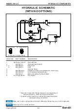
Страница 86: ...12 MODEL 200 UC SPECIFIC SCHEMATIC FUNCTION MAY VARY DEPENDING ON OPTIONS OR COMPONENT MANUFACTURE WITH NO OPTIONS HYDRAULIC SECTION FEEDWHEEL MOTOR FEEDWHEEL MOTOR FLOW DIVIDER CONTROL VALVE PUMP SUCTION SCREEN FILTER TANK ...

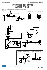
Страница 87: ...CTION MAY VARY DEPENDING ON OPTIONS OR COMPONENT MANUFACTURE WITH AUTOFEED PLUS YOKE LIFT HYDRAULIC SECTION FEEDWHEEL MOTOR FEEDWHEEL MOTOR FLOW DIVIDER CONTROL VALVE FILTER TANK SUCTION SCREEN PUMP AUTOFEED VALVE CONTROL VALVE REVERSING VALVE YOKE LIFT CYLINDER ...

Страница 88: ... flow Anything causing an obstruction will cause the chute to plug D Chipping rotting material that has little substance can also plug the discharge chute E Worn fan blades 4 Chipper Bearings Running Too Hot A Improper lubrication purge bearings once a day with EP 2 Lithium type grease B Chipper disc operating at too high RPM s DO NOT exceed recommended RPM s C Check the chipper bearing locking co...

Страница 89: ...und to produce a flat straight edge Do not sharpen the knives with a hand held power grinder The knife angle can t be held and heat will distort the metal Sharpening techniques should be the same as those employed for any high carbon steel cutting edge Use a coolant and exercise care not to draw temper or crack the cutting edges by excessive heating Knives may be sharpened repeatedly as long as th...

Страница 90: ...isc chippers or the condition of the knife bolt threads on drum chippers If a problem is found contact your local dealer or Bandit Industries 8 Clean out the knife pocket at this time Remove all debris from the pocket and knife bolt holes 9 Sharpen rotate or replace the chipper knife Knives should be professionally ground maintaining angle and dimensional specifications Knives should be replaced i...

Страница 91: ...se feedwheel bearings daily with one shot of grease Both types of bearings are designed with a relief system that will not allow over greasing In other words you can not hurt the bearing seals by pumping in too much grease Wipe off excess grease Excessive grease will attract dirt Most of the failures related to bearings are diagnosed as Contamination Contamination is caused by improper lubrication...

Страница 92: ...lack BL Power to Breakaway Switch WIRING FOR STANDARD 6 PRONG PLUG AND 6 WIRE MAIN CABLE EFFECTIVE ON MACHINES BUILT AFTER 11 01 04 BATTERY BREAKAWAY SWITCH BLACK TO RED WIRE ON MAIN CABLE WIRE MAIN CABLE 6 J R JUNCTION BOX WIRES SPLICED TOGETHER WHITE WIRES GROUNDED J R BLACK R ELECTRIC BRAKES ELECTRIC BRAKES BL BL W W BR BR BR G Y LICENSE PLATE LIGHT AMBER MARKER LIGHT RED MARKER LIGHT TAILLIGHT...

Страница 93: ...s in models size design installations and applications on any part without notification All nuts bolts washers and many other components can be ordered by physical description When ordering any replacement parts you should have the serial number S N and model of the machine to ensure that you receive the correct replacement part See page 6 for typical serial number work order number locations Some...

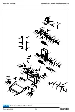
Страница 94: ...Bandit 78 Copyright 6 12 MODEL 200 UC INFEED HOPPER COMPONENTS Parts may not be exactly as shown NOTICE ...

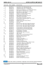
Страница 95: ... Wide Infeed Hopper 13 980 0137 06 Folding Pan Lock Tab For 1 2 Diameter Pin 14 a 980 200176 Tail Light Mount Road Side b 980 200177 Tail Light Mount Curb Side 15 900 2924 49 LED Red Marker Light 3 4 Round 16 a 900 2908 76 LED Tail Light b 900 2908 74 Adapter Wire for LED Tail Light Not Shown 17 900 2908 75 Rubber Grommet for LED Tail Light 18 980 2002 82 Heavy Duty Tail Light Cover 19 900 4914 18...

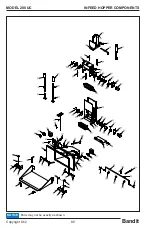
Страница 96: ...Bandit 80 Copyright 6 12 MODEL 200 UC INFEED HOPPER COMPONENTS Parts may not be exactly as shown NOTICE ...

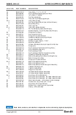
Страница 97: ...Ports 51 a 986 0501 74 Top Feedwheel Assembly b 980 300207 Top Feedwheel Tooth c 986 0501 73 Top Feedwheel Shaft Coupler Assembly 52 980 200114 Feedwheel Slide Box Assembly 53 900 3944 21 Bottom Feedwheel Hyd Motor O Ring Ports 54 a 980 300514 Bottom Torque Arm Stop b 937 300316 Torque Arm Cushion Mount 55 a 986 0501 75 Bottom Feedwheel Assembly b 980 300207 Bottom Feedwheel Tooth c 986 0501 73 Bo...

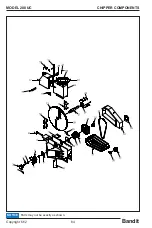
Страница 98: ...Bandit 82 Copyright 6 12 MODEL 200 UC CHIPPER COMPONENTS Parts may not be exactly as shown NOTICE ...

Страница 99: ...ade Assembly 15 a 900 4908 27 Discharge Spring Lock b 900 7900 96 Rubber Cap Not Shown 16 980 0133 62 Hood Hinge 17 980 100006 Chipper Hood Hinged Half 18 a 980 0509 04 Engine Disable Plug Kit Includes Hood Pin Mounts b 900 2904 13 6 Prong Female Plug Only c 980 100083 6 Prong Male Plug With Wire Loop Crimp Sleeves 19 a 980 0508 54 Spring Lock For Hood Pin b 900 7900 93 Black Vinyl Cap Not Shown 2...

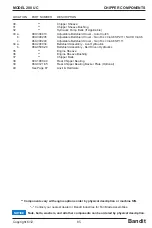
Страница 100: ...Bandit 84 Copyright 6 12 MODEL 200 UC CHIPPER COMPONENTS Parts may not be exactly as shown NOTICE ...

Страница 101: ... a 980 200034 Beltshield Assembly Live Hydraulics b 980 0500 24 Beltshield Assembly Belt Driven Hydraulics 35 Engine Sheave 36 Engine Sheave Bushing 37 Chipper Belts 38 900 1900 34 Rear Chipper Bearing 39 980 0121 65 Rear Chipper Bearing Backer Plate Optional 40 See Page 87 Anvil Hardware Nuts bolts washers and all other components can be ordered by physical description NOTICE Components vary with...

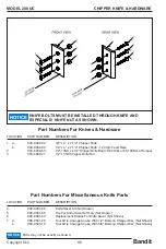
Страница 102: ...not be exactly as shown NOTICE Part Numbers For Knives Hardware Part Numbers For Miscellaneous Knife Parts LOCATION PART NUMBER DESCRIPTION 4 900 9901 68 Knife Saver Kit Not Shown 5 900 9901 65 File For Knife Saver Kit Only Not Shown 6 900 9901 63 Replacement Blades For Knife Saver Not Shown 7 a 986 0501 22 Tool Kit to Change Knives With 1 2 Bolts on Chipper Disc Not Shown b 980 0503 19 Tool Kit t...

Страница 103: ...00 74 1 2 13NC x 2 Hex Head Bolt 8 900 4906 72 1 2 13NC x 1 1 2 Hex Head Bolt 9 900 4906 82 1 2 13NC Hex Nut 10 900 4906 90 1 2 USS Flat Washer 11 980 0129 34 Anvil Puller Block 12 a 900 4906 41 5 16 18NC x 2 Hex Head Bolt b 900 4910 73 5 16 18NC Hex Nut 13 981 1006 16 Anvil Gauge 14 980 0508 97 Anvil Hardware Only Includes 2 Through 10 12 15 980 0507 77LD Anvil and Hardware Kit Includes 1 Through...

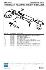
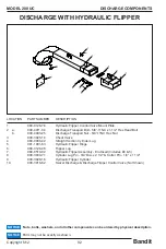
Страница 104: ...Plate Assembly For Enclosed Flipper 6 911 300124 Clean Out Door 7 a 900 4910 73 5 16 18NC Hex Nut b 900 4906 47 5 16 Lock Washer c 900 4906 48 5 16 Flat Washer 8 980 300349 Hood Flange 9 980 300424 Bottom Swivel Ring 10 a 900 4910 54 Discharge Transport Bolt 3 8 16NC x 1 1 2 Not Shown b 900 4906 60 Discharge Transport Nut 3 8 16NC Not Shown DISCHARGE COMPONENTS Parts may not be exactly as shown NO...

Страница 105: ...bly Includes 10 12 6 a 900 4901 83 Discharge Flipper Adjusting Spring b 900 7900 93 Black Rubber Cap Not Shown 7 a 980 0510 23 Adjusting Spring Lock Plate Assembly For Standard Flipper b 980 0510 24 Adjusting Spring Lock Plate Assembly For Enclosed Flipper 8 a 900 4910 54 Discharge Transport Bolt 3 8 16NC x 1 1 2 Not Shown b 900 4906 60 Discharge Transport Nut 3 8 16NC Not Shown DISCHARGE COMPONEN...

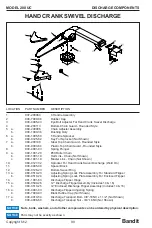
Страница 106: ...0127 32 Sprocket For Hand Crank Swivel Discharge Weld On 11 900 4905 00 Spacer Block 12 980 0128 23 Bottom Swivel Ring 13 a 980 0510 23 Adjusting Spring Lock Plate Assembly For Standard Flipper b 980 0510 24 Adjusting Spring Lock Plate Assembly For Enclosed Flipper 14 981 1001 63 Discharge Flipper Hinge 15 a 980 0509 26 12 Discharge Flipper Assembly Includes 14 16 b 980 0510 25 12 Enclosed Dischar...

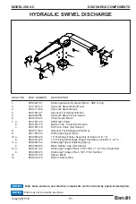
Страница 107: ...rocket For Discharge Weld On 9 981 1001 63 Discharge Flipper Hinge 10 a 980 0509 26 12 Discharge Flipper Assembly Includes 11 13 b 980 0510 25 12 Enclosed Discharge Flipper Assembly Includes 11 13 11 a 900 4901 83 Discharge Flipper Adjusting Spring b 900 7900 93 Black Rubber Cap Not Shown 12 a 900 4911 04 Discharge Transport Bolt 5 8 11NC x 1 1 2 Hex Head Bolt b 900 4903 25 Discharge Transport Nut...

Страница 108: ...on Cylinder Lug 5 981 1001 63 Hydraulic Flipper Hinge 6 980 0126 48 Flipper Lug 7 980 0510 02 Hydraulic Flipper Assembly Enclosed Includes 4 5 8 900 3930 71 Cylinder Lug Pin 3 4 Dia x 2 1 2 Cotter Pin 1 4 x 1 1 2 9 900 3928 16 Hydraulic Flipper Cylinder 10 900 3916 62 Swivel Discharge Discharge Flipper Control Valve Not Shown DISCHARGE COMPONENTS DISCHARGE WITH HYDRAULIC FLIPPER Parts may not be e...

Страница 109: ... Bottom Feedwheel Hydraulic Motor 8 See Pages 98 99 Flow Divider HYDRAULIC COMPONENTS HYDRAULIC SCHEMATIC WITH NO OPTIONS Parts may not be exactly as shown NOTICE Hydraulic components fittings hoses will very depending on optional equipment Order by physical description Hydraulic pumps need to be ordered by physical description and serial number of machine Make sure to order components according t...

Страница 110: ...actly as shown NOTICE Examples of straight fittings PIPE FITTING JIC SAE O RING 18 6 12 13 3 4 2 1 14 15 16 17 5 7 10 11 8 9 11 9 19 12 13 INSERT WITH YOKE LIFT WITHOUT AUTOFEED To Yoke Lift Valve From Hydraulic Pump 21 14 17 18 20 16 22 INSERT WITH YOKE LIFT WITHOUT AUTOFEED From Yoke Lift Valve To Relief Block ...

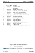
Страница 111: ...4 21 Bottom Feedwheel Hydraulic Motor 14 900 3921 57 Swivel Discharge Hydraulic Motor 15 900 3920 01 Swivel Discharge Control Valve Only 16 900 3920 01 Tongue Jack Control Valve 17 900 3949 09 Tongue Jack Check Valve 18 900 3934 24 Tongue Jack Cylinder Welded 19 900 3907 31 Relief Block Machines With Yoke Lift Without Autofeed 20 900 3916 62 Swivel Discharge Discharge Flipper Control Valve 21 900 ...

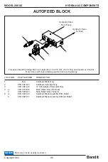
Страница 112: ... b 900 3908 23 Main Relief Only Vickers 5 a 900 3923 45 Autofeed Block Assembly With Relief b 900 3923 37 Autofeed Block Assembly Without Relief AUTOFEED BLOCK Parts may not be exactly as shown NOTICE HYDRAULIC COMPONENTS Torque Autofeed Cartridge Nut to a maximum of 4 to 6 ft lbs 5 to 8 Nm and install Loc Tite 241 Over torque will cause damage and will also void warranty Hydraulic Hose To Tank Hy...

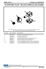
Страница 113: ...ck Subplate Edmore 6 4589960 Seal Kit For Danfoss Valve Not Shown 7 a 900 3925 89 10 Cord and Molded Herschman Connector Not Shown b 900 3920 71 16 Cord and Molded Herschman Connector Not Shown c 900 3918 63 25 Cord and Molded Herschman Connector Not Shown AUTOFEED PLUS VALVES SINGLE SOLENOID Parts may not be exactly as shown NOTICE HYDRAULIC COMPONENTS Torque Retainer Nut to a maximum of 4 to 6 f...

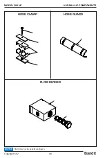
Страница 114: ...Bandit 98 Copyright 6 12 MODEL 200 UC HYDRAULIC COMPONENTS Parts may not be exactly as shown NOTICE HOSE CLAMP HOSE GUARD FLOW DIVIDER ...

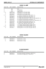
Страница 115: ...uble Clamp Assembly Includes s 1 4 f 900 3913 32 1 2 Double Clamp Assembly For Steel Lines Includes s 1 4 g 900 3914 03 3 4 Single Clamp Assembly Includes s 1 4 h 900 3914 07 3 4 Double Clamp Assembly Includes s 1 4 i 900 3914 04 1 Single Clamp Assembly Includes s 1 4 j 900 3914 05 1 1 4 Single Clamp Assembly Includes s 1 4 k 900 3914 06 1 1 2 Single Clamp Assembly Includes s 1 4 6 a 900 3914 10 S...

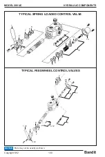
Страница 116: ... 12 MODEL 200 UC 1 2 3 4 6 7 8 9 10 11 12 13 6 6 6 7 9 TYPICAL FEEDWHEEL CONTROL VALVES TYPICAL SPRING LOADED CONTROL VALVE 11 9 8 4 12 6 6 7 2 1 12 3 12 6 6 7 10 HYDRAULIC COMPONENTS Parts may not be exactly as shown NOTICE ...

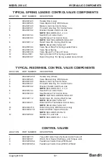
Страница 117: ...CAL FEEDWHEEL CONTROL VALVE COMPONENTS LOCATION PART NUMBER DESCRIPTION 1 900 3905 95H Handle Only Short 2 900 3905 95 Valve Bracket Only With Screws 3 904 0003 30 Master Link Only Control Valve 4 904 0003 31 Pin And Cotter Key For Control Valve 5 904 0003 32 Bracket Handle And Chain Link NOTE INCLUDES s 1 2 3 4 6 900 3937 34 Seal Kit For Control Valve 7 904 0003 33 Seal Retainer For Control Valve...

Страница 118: ...Bandit 102 Copyright 6 12 MODEL 200 UC FRAME ACCESSORY COMPONENTS Parts may not be exactly as shown NOTICE OPTIONAL SLIDING TONGUE ...

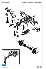
Страница 119: ...ner Box for 660 1010 CCA Battery 11 a 900 7900 78B Aluminum Battery Box For 660 1010 CCA Battery And Manual Holder b 980 0509 37 Steel Battery Box For 660 1010 CCA Battery And Manual Holder 12 900 2924 50 LED Amber Marker Light 3 4 Round 13 a 900 5904 43 Aluminum Fender b 980 0506 82 Right Hand HD Steel Bolt On Fender c 980 0506 84 Left Hand HD Steel Bolt On Fender 14 980 0128 14 Aluminum Fender M...

Страница 120: ...Bandit 104 Copyright 6 12 MODEL 200 UC FRAME ACCESSORY COMPONENTS Parts may not be exactly as shown NOTICE OPTIONAL SLIDING TONGUE ...

Страница 121: ...t Rim Only d 900 5904 20 245 75R 16 Tire and White Spoke 8 Bolt Rim e 900 5904 18 245 75R 16 Tire Only f 900 5904 22 16 x 6 White Spoke 8 Bolt Rim Only 29 a 900 5905 23 5 200 Lb Torflex Axle Assembly Electric Brake E Z Lube b 900 5905 60 7 000 Lb Torflex Axle Assembly Electric Brake E Z Lube 30 Brake Hub and Drum Assembly 31 d 980 0508 43 Telescopic Tongue Assembly 32 a 980 0508 25 Optional Wheel ...

Страница 122: ...Bandit 106 Copyright 6 12 MODEL 200 UC Parts may not be exactly as shown NOTICE FUEL HYDRAULIC TANK COMPONENTS ...

Страница 123: ... Hose Barb e 900 3943 22 3 16 NPTF To 3 16 Hose Barb f 900 3943 21 1 4 NPTF To 3 16 NPTF Bushing 10 a 900 3926 84 SuctionDropPipeAss yWithoutHoseBarb 1 2 NPTFMalex3 8 NPTFFemale b 900 3926 83 3 8 NPTF To 1 2 Hose Barb c 900 3926 82 3 8 NPTF To 3 8 Hose Barb d 900 3931 53 3 8 NPTF To 5 16 Hose Barb 11 900 3908 92 24 1 2 Gallon Rectangle Plastic Fuel Tank 12 980 0508 50 Fill Cap Lock Assembly For Pl...

Страница 124: ...CHANCE LOCATION PART NUMBER DESCRIPTION 1 980 300185 Hydraulic Last Chance Control Bar 2 a 900 7900 96 Vinyl Grip Black b 900 7901 41 Vinyl Grip Yellow 3 900 3914 02 Control Handle Pivot Bracket 4 900 4907 43 Cables 5 955 300054 Linkage Nuts bolts washers and all other components can be ordered by physical description NOTICE ...

Страница 125: ...4 0006 90 Seal Kit Welded Lift Cylinder Not Shown 7 900 3927 73 Yoke Lift Control Valve For Dual Control Yoke Lift 8 900 3920 05A Feedwheel Control Valve Without Relief SAE O ring 9 900 3954 43 Hydraulic Activated Last Chance Valve 10 See Page 97 Reversing Autofeed Plus 11 See Pages 98 99 Flow Divider 12 900 3920 30 Top Feedwheel Hydraulic Motor 13 900 3944 21 Bottom Feedwheel Hydraulic Motor Hydr...

Страница 126: ...Bandit 110 Copyright 6 12 MODEL 200 UC SERVICE RECORD SERVICE RECORD DATE DESCRIPTION AMOUNT ...

Отзывы: