-48-
5. Operation of main
motor is not stable,
maximum speed
operation is not
possible, or speed
cannot be adjusted.
1) When turning on power and moving speed slide, does
voltage between pins 3 and 1 of connector CN9 (for
speed slide) change from 0 to 5 VDC?
2) When turning balance wheel opposite its normal
rotation direction, do voltages between pins 2-1, pins
4-1, pins 5-1, and 6-1 of connector CN15 (for NP
board) change to either 0 or 5 VDC?
3) Others
1) Replace (SS) VR board assembly.
2) Replace NP board assembly.
3) Replace main PC board.
6. Correct patterns are not
created.
1) If the power is turned off and the needle bar is moved
horizontally by hand, does it move easily?
2) Is the N.P. shutter in the correct position?
3) Are the resistances between the connector pins for
the zigzag, feed and horizontal pulse motors normal?
Zigzag (CN13)................ 1-3,
2-4
®
8-10
W
Feed (CN16)................ 1-3,
2-4
®
8-10
W
Horizontal (CN17)................ 1-3, 2-4
®
8-10
W
4) Do the voltages between pins 2-1, 5-1 and 6-1 of the
N.P. board assembly connector (CN15) alternate
between 0-5 VDC when the sewing machine is turned
slowly in reverse?
5) Others
1) Adjust the installation position so
that it moves easily.
2) Adjust N.P. shutter position.
3) Replace pulse motor or lead wire
assembly.
4) Replace NP board assembly.
5) Replace main PC board assembly.
7. Buttonholes are not
stitched correctly.
1) Is the stitch foot set correctly?
2) Is the resistance between pins 4-5 of the junction
board BH connector (CN10) normal?
When buttonhole lever is lowered .... 1
W
or less
When buttonhole lever is raised ........................
¥
3) When the buttonhole lever is lowered and in the
conditions below, is the resistance between pins 1-2
and 2-3 of the junction board connector (CN10)
normal?
Between 1-2 Between 2-3
Buttonhole lever is
pulled forward...................1
W
or less
¥
Buttonhole lever is
pushed back.....................
¥
1
W
or less
4) Others
1) Check stitch foot.
2) Adjust button hole lever or replace
BH switch assembly.
3) Adjust button hole lever or replace
BH switch assembly.
4) Replace main PC board assembly.
8. Manual operation of
feed and zigzag pulse
motors is not possible.
1) Do manual keys of feed and zigzag pulse motors turn
off and on normally, and do the LCDs change?
2) Are the resistances between the pins below of the
feed and zigzag pulse motors normal?
Feed
(CN13)................ 1-3, 2-4
®
8-10
W
Zigzag
(CN10)................ 1-3, 2-4
®
8-10
W
3) Others
1) Replace LCD module.
2) Replace feed stepping motor, zigzag
stepping motor or lead wire
assembly.
3) Replace main PC board assembly.
9. Vertical movement of
needle bar and
backstitch operation
are abnormal.
1) Are the resistances between both sides of the SS PC
board assembly switches 1
W
or less and in the k
W
range respectively when the switches are turned off
and on?
2) Is the position of the NP shutter normal?
3) Do the voltages between pins 2-1, 4-1, 5-1 and 6-1 of
the NP board assembly connector (CN4) alternate
between 0-5V when the sewing machine is turned
slowly in reverse?
4) Is the bobbin winder switch turned off?
5) Others
1) Replace SS PC board assembly.
2) Adjust N.P. shutter position.
3) Replace NP board assembly.
4) Adjust the bobbin winder
mechanism.
5) Replace main PC board assembly.
10. Foot controller does not
operate normally when
depressed.
1) Is the resistance between pins 2-3 of the pin jack
connector (CN1) 1
W
or less when there is no pin jack
and
¥
when there is a pin jack?
2) Does the resistance between pins 1-3 of the pin jack
connector (CN1) change from the low
W
range to 10 k
W
when there is a pin jack and the foot controller is
depressed?
3) Others
1) Replace pin jack assembly.
2) Replace foot controller.
3) Replace main PC board assembly.
Содержание PC8200 SUPER GALAXIE 2000
Страница 1: ...SERVICE MANUAL FOR COMPUTERIZED SEWING MACHINE PC8200 SUPER GALAXIE 2000 9 1997 ...
Страница 4: ... 2 1 MECHANICAL CHART EMBROIDERY UNIT MECHANISM ...
Страница 6: ... 4 3 ELECTRONIC PARTS ARRANGEMENT CHART PC 8200 Model 985 4 CONTROL SYSTEM BLOCK DIAGRAM ...
Страница 16: ... 14 ...
Страница 18: ... 16 ...
Страница 20: ... 18 ...
Страница 23: ... 21 2 LEAD WIRE ARRANGEMENT PC 8200 Model 985 ...
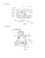
Страница 53: ... 51 Main PC board Power supply unit ...
Страница 54: ... 52 LCD unit Other PC boards 985 ...
Страница 55: ... 53 PC8200 SG2000 H7070093 ...

