


-12-
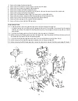
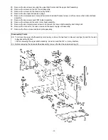
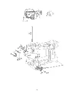
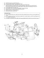
28. Remove the two screws securing the upper shaft metal, and the upper shaft assembly.
29. Remove the screw and the N.P. board assembly.
30. Remove the screw and the tension pulley holder.
31. Remove the two feed rod tension springs.
32. Remove the metal presser screw and horizontal feed shaft bracket screw, and then remove the horizontal feed
assembly.
33. Remove the two screws and FPM holder assembly.
34. Remove the screw and the outer rotary hook assembly.
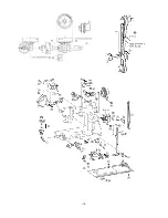
35. Remove the two metal presser screws, and remove the lower shaft assembly and timing belt.
36. Remove the connector, the two screws and the power supply unit assembly.
37. Remove the three screws and base plate assembly.
Disassembly Points
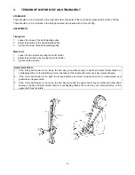
28. To remove the upper shaft assembly more easily, remove the two feed rod tension springs (A) and the tension
pulley assembly (B) first.
*
When removing the upper shaft assembly, do not to bend the N.P. or rotary shutters.
32. Before removing the horizontal feed assembly, remove the feed bar tension spring (C).
Содержание PC8200 SUPER GALAXIE 2000
Страница 1: ...SERVICE MANUAL FOR COMPUTERIZED SEWING MACHINE PC8200 SUPER GALAXIE 2000 9 1997 ...
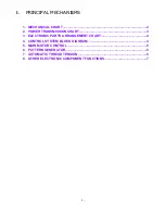
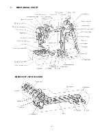
Страница 4: ... 2 1 MECHANICAL CHART EMBROIDERY UNIT MECHANISM ...
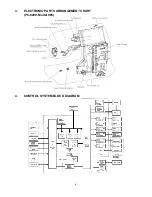
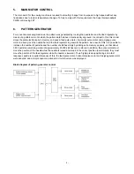
Страница 6: ... 4 3 ELECTRONIC PARTS ARRANGEMENT CHART PC 8200 Model 985 4 CONTROL SYSTEM BLOCK DIAGRAM ...
Страница 16: ... 14 ...
Страница 18: ... 16 ...
Страница 20: ... 18 ...
Страница 23: ... 21 2 LEAD WIRE ARRANGEMENT PC 8200 Model 985 ...
Страница 53: ... 51 Main PC board Power supply unit ...
Страница 54: ... 52 LCD unit Other PC boards 985 ...
Страница 55: ... 53 PC8200 SG2000 H7070093 ...


