


4-27
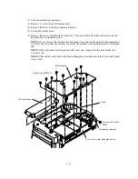
Reassembling Notes
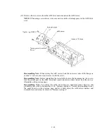
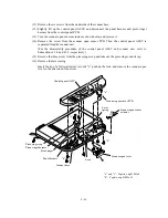
• When setting the document tray on the scanner unit, pass the bound harnesses (ADF motor
harness, document sensor harness, document tray open sensor harness, and grounding wire)
through the front section of the opening provided in the left rear corner of the document tray,
with its bound section facing up (see the illustration given on page 4-25).
Move those bound harnesses to the rear section of the opening. Route the bound section
through the cable guide so that the cable binder comes into contact with the cable guide as
illustrated on page 4-25. Refer to Subsection 4.1.26 "Harness routing A."
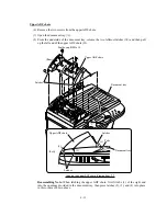
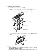
• When putting the scanner unit on the scanner mount, take special care not to bend, wrinkle, or
scratch the CCD flat cable or not to break the boss of the main cover by the bottom of the
scanner unit. (See the illustration given on page 4-24.)
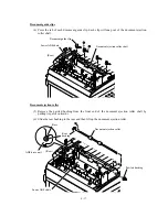
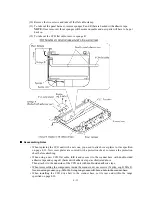
• Connect the document sensor harness, document tray open sensor harness, ADF motor harness,
and panel harness to the relay PCB, and secure the two grounding wires to the main cover as
shown in Subsection 4.1.26, "Harness routing B."
Содержание MFC-5100C
Страница 1: ...FACSIMILE EQUIPMENT SERVICE MANUAL MODEL MFC5100C MFC590 ...
Страница 4: ...CHAPTER 1 GENERAL DESCRIPTION ...
Страница 11: ...CHAPTER 2 INSTALLATION ...
Страница 19: ...CHAPTER 3 THEORY OF OPERATION ...
Страница 39: ...CHAPTER 4 DISASSEMBLY REASSEMBLY LUBRICATION AND ADJUSTMENT ...
Страница 73: ...4 32 8 Remove the three screws and lift up the guide plate 9 Remove the screw from the CCD HP sensor plate ...
Страница 109: ...4 68 Harness routing E Head flat cables on the lower cover PCB plate Head flat cables Ferrite core Main PCB ...
Страница 112: ...4 71 4 ASF roller unit 5 Main cover Apply thin coat of grease to these two sections with a brush HP HP Main cover ...
Страница 114: ...4 73 7 Paper ejection roller gear and PF roller gear 8 Paper feed roller and PF spring ...
Страница 116: ...4 75 11 Purge shaft ...
Страница 119: ...4 78 Head Positioning Test Pattern ...
Страница 120: ...CHAPTER 5 MAINTENANCE MODE ...
Страница 127: ...5 6 Scanning Compensation Data List ...
Страница 141: ...5 20 Vertical Alignment Check Pattern ...
Страница 148: ...CHAPTER 6 ERROR INDICATION AND TROUBLESHOOTING ...
Страница 173: ...MFC5100C MFC590 Appendix 1 EEPROM Customizing Codes ...
Страница 176: ...MFC5100C MFC590 Appendix 2 Firmware Switches WSW ...
Страница 220: ...A Main PCB 1 6 ...
Страница 221: ...A Main PCB 2 6 ...
Страница 222: ...A Main PCB 3 6 ...
Страница 223: ...A Main PCB 4 6 ...
Страница 224: ...A Main PCB 5 6 ...
Страница 225: ...A Main PCB 6 6 ...
Страница 226: ...R27 100 R28 100 R29 100 R30 100 B Relay PCB ...
Страница 227: ...C NCU PCB ...
Страница 228: ...D Control Panel PCB 1 2 ...
Страница 229: ...D Control Panel PCB 2 2 ...
Страница 230: ...E Power Supply PCB ...
Страница 231: ...Jan 02 SM FAX005R 8CA401 Printed in Japan ...


