


10
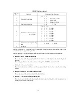
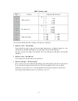
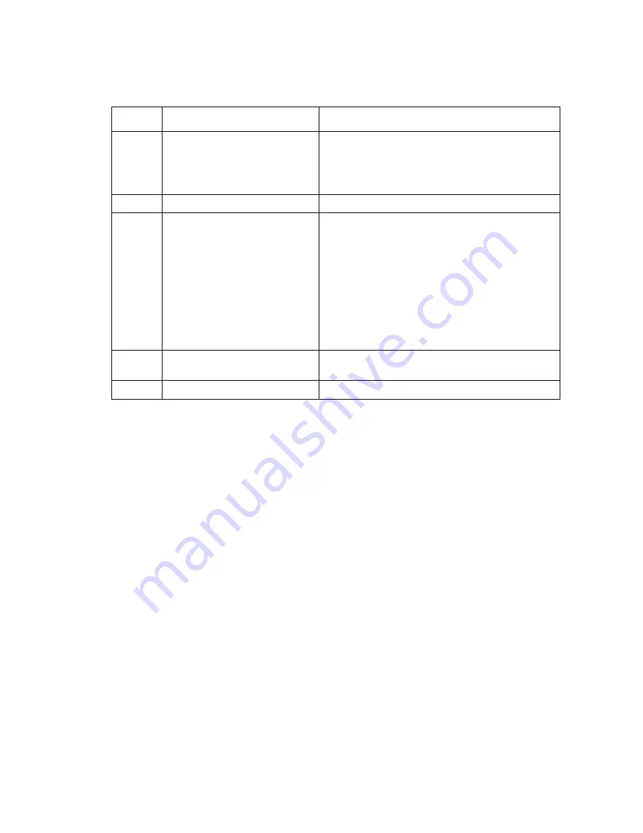
WSW07
(Dial tone setting 1)
Selector
No.
Function
Setting and Specifications
1
2
Frequency band range
No. 1 2
0 0
: Narrows by 10 Hz
0 1
: Initial
value
1 X
: Widens by 10 Hz
3
Line current detection
0: No
1: Yes
4
|
6
2nd dial tone detection level
(Z = 600
Ω
)
No. 4 5 6
0
0 0 : -21
dBm
0
0 1 : -24
dBm
0
1 0 : -27
dBm
0
1 1 : -30
dBm
1
0 0 : -33
dBm
1
0 1 : -36
dBm
1
1 0 : -39
dBm
1
1 1 : -42
dBm
7
1st dial tone interrupt detecting
time
0: 30 ms
1: 50 ms
8
Not used.
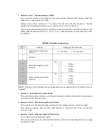
NOTE:
Selectors 1, 2, 4 through 7 are not applicable in those countries where no dial tone or line
current detection is supported, e.g., U.S.A.
NOTE:
Selector 3 is not applicable to those models having no loop current detection function.
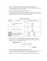
Selectors 1 and 2: Frequency band range
These selectors set the frequency band for the 1st dial tone and the busy tone (before dialing) to be
detected.
This setting is effective only when selectors 1 through 3 of WSW05 are set to "1,1,1."
Selector 3:
Line current detection
This selector determines whether or not the equipment should detect a line current before starting
dialing.
Selectors 4 through 6: 2nd dial tone detection level
These selectors set the detection level of the 2nd dial tone.
Selector 7:
1st dial tone interrupt detecting time
This selector sets the allowable time length of an interrupt which should not be interpreted as an
interrupt in the 1st dial tone dialing.
Содержание MFC-5100C
Страница 1: ...FACSIMILE EQUIPMENT SERVICE MANUAL MODEL MFC5100C MFC590 ...
Страница 4: ...CHAPTER 1 GENERAL DESCRIPTION ...
Страница 11: ...CHAPTER 2 INSTALLATION ...
Страница 19: ...CHAPTER 3 THEORY OF OPERATION ...
Страница 39: ...CHAPTER 4 DISASSEMBLY REASSEMBLY LUBRICATION AND ADJUSTMENT ...
Страница 73: ...4 32 8 Remove the three screws and lift up the guide plate 9 Remove the screw from the CCD HP sensor plate ...
Страница 109: ...4 68 Harness routing E Head flat cables on the lower cover PCB plate Head flat cables Ferrite core Main PCB ...
Страница 112: ...4 71 4 ASF roller unit 5 Main cover Apply thin coat of grease to these two sections with a brush HP HP Main cover ...
Страница 114: ...4 73 7 Paper ejection roller gear and PF roller gear 8 Paper feed roller and PF spring ...
Страница 116: ...4 75 11 Purge shaft ...
Страница 119: ...4 78 Head Positioning Test Pattern ...
Страница 120: ...CHAPTER 5 MAINTENANCE MODE ...
Страница 127: ...5 6 Scanning Compensation Data List ...
Страница 141: ...5 20 Vertical Alignment Check Pattern ...
Страница 148: ...CHAPTER 6 ERROR INDICATION AND TROUBLESHOOTING ...
Страница 173: ...MFC5100C MFC590 Appendix 1 EEPROM Customizing Codes ...
Страница 176: ...MFC5100C MFC590 Appendix 2 Firmware Switches WSW ...
Страница 220: ...A Main PCB 1 6 ...
Страница 221: ...A Main PCB 2 6 ...
Страница 222: ...A Main PCB 3 6 ...
Страница 223: ...A Main PCB 4 6 ...
Страница 224: ...A Main PCB 5 6 ...
Страница 225: ...A Main PCB 6 6 ...
Страница 226: ...R27 100 R28 100 R29 100 R30 100 B Relay PCB ...
Страница 227: ...C NCU PCB ...
Страница 228: ...D Control Panel PCB 1 2 ...
Страница 229: ...D Control Panel PCB 2 2 ...
Страница 230: ...E Power Supply PCB ...
Страница 231: ...Jan 02 SM FAX005R 8CA401 Printed in Japan ...


