


27
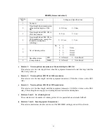
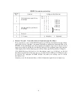
WSW26
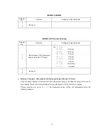
(Function setting 4)
Selector
No.
Function
Setting and Specifications
1
2
Not used.
3
Dialing during document
reading into the temporary
memory in in-memory message
transmission
0: Disabled 1: Enabled
4
5
No. of CNG cycles to be
detected
(when the line is connected via
the external telephone except in
the external TAD mode or via
the built-in telephone)
No. 4
5
0
0
:
0.5
(A)
0
1
:
1
(B)
1
0
:
1.5
(C)
1
1
:
2
(D)
6
7
No. of CNG cycles to be
detected
(when the line is connected via
the external telephone in the
external TAD mode or via the
facsimile equipment in F/T
mode)
No. 6
7
0
0
:
0.5
(A)
0
1
:
1
(B)
1
0
:
1.5
(C)
1
1
:
2
(D)
8
Not used.
Selector 3: Dialing during document reading into the temporary memory in in-memory message
transmission
If this selector is set to "0," the facsimile equipment waits for document reading into the memory
to complete and then starts dialing. This enables the equipment to list the total number of pages in
the header of the facsimile message.
Selectors 4 and 5: No. of CNG cycles to be detected
The equipment interprets a CNG as an effective signal if it detects a CNG signal by the number of
cycles specified by these selectors when the line is connected via the external telephone except in
the external TAD mode or via the built-in telephone.
Selectors 6 and 7: No. of CNG cycles to be detected
The equipment interprets a CNG as an effective signal if it detects a CNG signal by the number of
cycles specified by these selectors when the line is connected via the external telephone in the
external TAD mode or via the facsimile equipment in F/T mode.
Содержание MFC-5100C
Страница 1: ...FACSIMILE EQUIPMENT SERVICE MANUAL MODEL MFC5100C MFC590 ...
Страница 4: ...CHAPTER 1 GENERAL DESCRIPTION ...
Страница 11: ...CHAPTER 2 INSTALLATION ...
Страница 19: ...CHAPTER 3 THEORY OF OPERATION ...
Страница 39: ...CHAPTER 4 DISASSEMBLY REASSEMBLY LUBRICATION AND ADJUSTMENT ...
Страница 73: ...4 32 8 Remove the three screws and lift up the guide plate 9 Remove the screw from the CCD HP sensor plate ...
Страница 109: ...4 68 Harness routing E Head flat cables on the lower cover PCB plate Head flat cables Ferrite core Main PCB ...
Страница 112: ...4 71 4 ASF roller unit 5 Main cover Apply thin coat of grease to these two sections with a brush HP HP Main cover ...
Страница 114: ...4 73 7 Paper ejection roller gear and PF roller gear 8 Paper feed roller and PF spring ...
Страница 116: ...4 75 11 Purge shaft ...
Страница 119: ...4 78 Head Positioning Test Pattern ...
Страница 120: ...CHAPTER 5 MAINTENANCE MODE ...
Страница 127: ...5 6 Scanning Compensation Data List ...
Страница 141: ...5 20 Vertical Alignment Check Pattern ...
Страница 148: ...CHAPTER 6 ERROR INDICATION AND TROUBLESHOOTING ...
Страница 173: ...MFC5100C MFC590 Appendix 1 EEPROM Customizing Codes ...
Страница 176: ...MFC5100C MFC590 Appendix 2 Firmware Switches WSW ...
Страница 220: ...A Main PCB 1 6 ...
Страница 221: ...A Main PCB 2 6 ...
Страница 222: ...A Main PCB 3 6 ...
Страница 223: ...A Main PCB 4 6 ...
Страница 224: ...A Main PCB 5 6 ...
Страница 225: ...A Main PCB 6 6 ...
Страница 226: ...R27 100 R28 100 R29 100 R30 100 B Relay PCB ...
Страница 227: ...C NCU PCB ...
Страница 228: ...D Control Panel PCB 1 2 ...
Страница 229: ...D Control Panel PCB 2 2 ...
Страница 230: ...E Power Supply PCB ...
Страница 231: ...Jan 02 SM FAX005R 8CA401 Printed in Japan ...


