


5-10
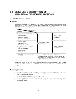
5.3.6 Firmware Switch Setting and Printout
[ A ] Firmware switch setting
Function
The facsimile equipment incorporates the following firmware switch functions which may be
activated with the procedures using the control panel keys and buttons.
The firmware switches have been set at the factory in conformity to the communications standards
and codes of each country. Do not disturb them unless necessary. Some firmware switches may not
be applicable in some versions. The firmware switch data list indicates "Not used." for those
inapplicable switches.
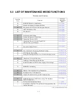
Firmware Switches (WSW01 through WSW50)
WSW No.
Function
WSW01
Dial pulse setting
WSW02
Tone signal setting
WSW03
PABX mode setting
WSW04
TRANSFER facility setting
WSW05
1st dial tone and busy tone detection
WSW06
Pause
key setting and 2nd dial tone detection
WSW07
Dial tone setting 1
WSW08
Dial tone setting 2
WSW09
Protocol definition 1
WSW10
Protocol definition 2
WSW11
Busy tone setting
WSW12
Signal detection condition setting
WSW13
Modem setting
WSW14
AUTO ANS facility setting
WSW15
REDIAL facility setting
WSW16
Function setting 1
WSW17
Function setting 2
WSW18
Function setting 3
WSW19
Transmission speed setting
WSW20
Overseas communications mode setting
WSW21
TAD setting 1
WSW22
ECM and copy resolution setting
WSW23
Communications setting
WSW24
TAD setting 2
WSW25
TAD setting 3
WSW26
Function setting 4
WSW27
Function setting 5
WSW28
Function setting 6
WSW29
Function setting 7
WSW30
Not used.
WSW31
Function setting 9
WSW32
Function setting 10
WSW33
Function setting 11
Содержание MFC-5100C
Страница 1: ...FACSIMILE EQUIPMENT SERVICE MANUAL MODEL MFC5100C MFC590 ...
Страница 4: ...CHAPTER 1 GENERAL DESCRIPTION ...
Страница 11: ...CHAPTER 2 INSTALLATION ...
Страница 19: ...CHAPTER 3 THEORY OF OPERATION ...
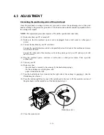
Страница 39: ...CHAPTER 4 DISASSEMBLY REASSEMBLY LUBRICATION AND ADJUSTMENT ...
Страница 73: ...4 32 8 Remove the three screws and lift up the guide plate 9 Remove the screw from the CCD HP sensor plate ...
Страница 109: ...4 68 Harness routing E Head flat cables on the lower cover PCB plate Head flat cables Ferrite core Main PCB ...
Страница 112: ...4 71 4 ASF roller unit 5 Main cover Apply thin coat of grease to these two sections with a brush HP HP Main cover ...
Страница 114: ...4 73 7 Paper ejection roller gear and PF roller gear 8 Paper feed roller and PF spring ...
Страница 116: ...4 75 11 Purge shaft ...
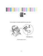
Страница 119: ...4 78 Head Positioning Test Pattern ...
Страница 120: ...CHAPTER 5 MAINTENANCE MODE ...
Страница 127: ...5 6 Scanning Compensation Data List ...
Страница 141: ...5 20 Vertical Alignment Check Pattern ...
Страница 148: ...CHAPTER 6 ERROR INDICATION AND TROUBLESHOOTING ...
Страница 173: ...MFC5100C MFC590 Appendix 1 EEPROM Customizing Codes ...
Страница 176: ...MFC5100C MFC590 Appendix 2 Firmware Switches WSW ...
Страница 220: ...A Main PCB 1 6 ...
Страница 221: ...A Main PCB 2 6 ...
Страница 222: ...A Main PCB 3 6 ...
Страница 223: ...A Main PCB 4 6 ...
Страница 224: ...A Main PCB 5 6 ...
Страница 225: ...A Main PCB 6 6 ...
Страница 226: ...R27 100 R28 100 R29 100 R30 100 B Relay PCB ...
Страница 227: ...C NCU PCB ...
Страница 228: ...D Control Panel PCB 1 2 ...
Страница 229: ...D Control Panel PCB 2 2 ...
Страница 230: ...E Power Supply PCB ...
Страница 231: ...Jan 02 SM FAX005R 8CA401 Printed in Japan ...


