


6-14
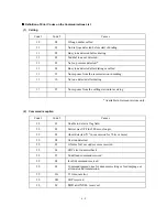
(11) General communications-related
Code 1
Code 2
Causes
B0
02
Unable to receive the next-page data.
B0
03
Unable to receive polling even during turn-around transmission
due to call reservation.
B0
04
PC interface error.
(12) Maintenance mode
Code 1
Code 2
Causes
E0
01
Failed to detect 1300 Hz signal in burn-in operation.
E0
02
Failed to detect PB signals in burn-in operation.
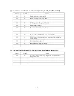
(13) Equipment error
Code 1
Code 2
Causes
FF
X X
Equipment error (For X X, refer to Subsection 6.1.1 [ 2 ].)
Содержание MFC-5100C
Страница 1: ...FACSIMILE EQUIPMENT SERVICE MANUAL MODEL MFC5100C MFC590 ...
Страница 4: ...CHAPTER 1 GENERAL DESCRIPTION ...
Страница 11: ...CHAPTER 2 INSTALLATION ...
Страница 19: ...CHAPTER 3 THEORY OF OPERATION ...
Страница 39: ...CHAPTER 4 DISASSEMBLY REASSEMBLY LUBRICATION AND ADJUSTMENT ...
Страница 73: ...4 32 8 Remove the three screws and lift up the guide plate 9 Remove the screw from the CCD HP sensor plate ...
Страница 109: ...4 68 Harness routing E Head flat cables on the lower cover PCB plate Head flat cables Ferrite core Main PCB ...
Страница 112: ...4 71 4 ASF roller unit 5 Main cover Apply thin coat of grease to these two sections with a brush HP HP Main cover ...
Страница 114: ...4 73 7 Paper ejection roller gear and PF roller gear 8 Paper feed roller and PF spring ...
Страница 116: ...4 75 11 Purge shaft ...
Страница 119: ...4 78 Head Positioning Test Pattern ...
Страница 120: ...CHAPTER 5 MAINTENANCE MODE ...
Страница 127: ...5 6 Scanning Compensation Data List ...
Страница 141: ...5 20 Vertical Alignment Check Pattern ...
Страница 148: ...CHAPTER 6 ERROR INDICATION AND TROUBLESHOOTING ...
Страница 173: ...MFC5100C MFC590 Appendix 1 EEPROM Customizing Codes ...
Страница 176: ...MFC5100C MFC590 Appendix 2 Firmware Switches WSW ...
Страница 220: ...A Main PCB 1 6 ...
Страница 221: ...A Main PCB 2 6 ...
Страница 222: ...A Main PCB 3 6 ...
Страница 223: ...A Main PCB 4 6 ...
Страница 224: ...A Main PCB 5 6 ...
Страница 225: ...A Main PCB 6 6 ...
Страница 226: ...R27 100 R28 100 R29 100 R30 100 B Relay PCB ...
Страница 227: ...C NCU PCB ...
Страница 228: ...D Control Panel PCB 1 2 ...
Страница 229: ...D Control Panel PCB 2 2 ...
Страница 230: ...E Power Supply PCB ...
Страница 231: ...Jan 02 SM FAX005R 8CA401 Printed in Japan ...


