


16
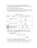
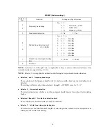
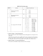
WSW13
(Modem setting)
Selector
No.
Function
Setting and Specifications
1
2
Cable equalizer
No. 1
2
0
0
:
0 km
0
1
: 1.8
km
1
0
:
3.6 km
1
1
:
5.6 km
3
4
Reception level
No. 3
4
0
0
:
-43 dBm
0
1
:
-47 dBm
1
0
:
-49 dBm
1
1
:
-51 dBm
5
|
8
Modem attenuator
0: 0 dB
1: 8 dB
0: 0 dB
1: 4 dB
0: 0 dB
1: 2 dB
0: 0 dB
1: 1 dB
The modem should be adjusted according to the user's line conditions.
Selectors 1 and 2: Cable equalizer
These selectors are used to improve the pass-band characteristics of analogue signals on a line.
(Attenuation in the high-band frequency is greater than in the low-band frequency.)
Set these selectors according to the distance from the telephone switchboard to the facsimile
equipment.
Selectors 3 and 4: Reception level
These selectors set the optimum receive signal level.
Selectors 5 through 8: Modem attenuator
These selectors are used to adjust the transmitting level of the modem when the reception level at
the remote station is improper due to line loss. This function applies for G3 protocol signals.
Setting two or more selectors to "1" produces addition of attenuation assigned to each selector.
This setting will be limited if selector 8 of WSW23 is set to "0."
Содержание MFC-5100C
Страница 1: ...FACSIMILE EQUIPMENT SERVICE MANUAL MODEL MFC5100C MFC590 ...
Страница 4: ...CHAPTER 1 GENERAL DESCRIPTION ...
Страница 11: ...CHAPTER 2 INSTALLATION ...
Страница 19: ...CHAPTER 3 THEORY OF OPERATION ...
Страница 39: ...CHAPTER 4 DISASSEMBLY REASSEMBLY LUBRICATION AND ADJUSTMENT ...
Страница 73: ...4 32 8 Remove the three screws and lift up the guide plate 9 Remove the screw from the CCD HP sensor plate ...
Страница 109: ...4 68 Harness routing E Head flat cables on the lower cover PCB plate Head flat cables Ferrite core Main PCB ...
Страница 112: ...4 71 4 ASF roller unit 5 Main cover Apply thin coat of grease to these two sections with a brush HP HP Main cover ...
Страница 114: ...4 73 7 Paper ejection roller gear and PF roller gear 8 Paper feed roller and PF spring ...
Страница 116: ...4 75 11 Purge shaft ...
Страница 119: ...4 78 Head Positioning Test Pattern ...
Страница 120: ...CHAPTER 5 MAINTENANCE MODE ...
Страница 127: ...5 6 Scanning Compensation Data List ...
Страница 141: ...5 20 Vertical Alignment Check Pattern ...
Страница 148: ...CHAPTER 6 ERROR INDICATION AND TROUBLESHOOTING ...
Страница 173: ...MFC5100C MFC590 Appendix 1 EEPROM Customizing Codes ...
Страница 176: ...MFC5100C MFC590 Appendix 2 Firmware Switches WSW ...
Страница 220: ...A Main PCB 1 6 ...
Страница 221: ...A Main PCB 2 6 ...
Страница 222: ...A Main PCB 3 6 ...
Страница 223: ...A Main PCB 4 6 ...
Страница 224: ...A Main PCB 5 6 ...
Страница 225: ...A Main PCB 6 6 ...
Страница 226: ...R27 100 R28 100 R29 100 R30 100 B Relay PCB ...
Страница 227: ...C NCU PCB ...
Страница 228: ...D Control Panel PCB 1 2 ...
Страница 229: ...D Control Panel PCB 2 2 ...
Страница 230: ...E Power Supply PCB ...
Страница 231: ...Jan 02 SM FAX005R 8CA401 Printed in Japan ...


