


ii
2.5.1 Charging ................................................................................... Refer to HL-730 (P.II-28)
2.5.2 Exposure stage......................................................................... Refer to HL-730 (P.II-29)
2.5.3 Developing................................................................................ Refer to HL-730 (P.II-30)
2.5.4 Transfer .................................................................................... Refer to HL-730 (P.II-30)
2.5.5 Drum Cleaning Stage ............................................................... Refer to HL-730 (P.II-31)
2.5.6 Erasing Stage ........................................................................... Refer to HL-730 (P.II-31)
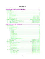
CHAPTER III DISASSEMBLY AND REASSEMBLY ................................................. III-1
3.1 Drum Unit................................................................................................................................. III-3
3.2 Top Cover ................................................................................................................................III-3
3.3 Multi-purpose Paper Tray Assy ..............................................................................................III-4
3.4 Fixing Unit ................................................................................................................................III-5
3.5 Scanner Unit ............................................................................................................................III-7
3.6 Main PCB Assy .......................................................................................................................III-7
3.7 Base Plate Assy.......................................................................................................................III-8
3.8 Panel sensor PCB Assy...........................................................................................................III-8
3.9 Low-voltage Power Supply PCB Assy .....................................................................................III-9
3.10 High-voltage Power Supply PCB Assy ....................................................................................III-9
3.11 Fan Motor................................................................................................................................. III-10
3.12 Drive Unit ................................................................................................................................. III-10
3.13 Main Motor Assy and Motor Heat Sink ....................................................................................III-11
3.14 Gears and Solenoid ...............................................................................................................III-11
3.15 Tray Extension .......................................................................................................................III-12
3.16 Paper Eject Tray Assy ...........................................................................................................III-12
3.17 Core ......................................................................................................................................III-13
1.1 Initial Check ............................................................................................ Refer to HL-730 (P.IV-1)
1.2 Basic Procedure ..................................................................................... Refer to HL-730 (P.IV-2)
2.1 Image Defect Examples.......................................................................... Refer to HL-730 (P.IV-3)
2.2 Troubleshooting Image Defects .............................................................. Refer to HL-730 (P.IV-4)
3. TROUBLESHOOTING OF MALFUNCTIONS ................................ Refer to HL-730 (P.IV-12)
4.1 Incorporated Inspection Modes .............................................................................................. IV-1
4.2 Error codes ............................................................................................................................. IV-3
Содержание HL-720
Страница 1: ...SERVICE MANUAL MODEL HL 720 730 730Plus R LASER PRINTER ...
Страница 36: ...II 19 1 3 10 Engine I O HL 720 Fig 2 21 shows the engine interface circuit Fig 2 21 ...
Страница 37: ...II 20 HL 730 730Plus Fig 2 22 shows the engine interface circuit Fig 2 22 ...
Страница 61: ... Fig 3 18 2 4 1 1 1 ...
Страница 92: ...SERVICE MANUAL MODEL HL 760 R LASER PRINTER ...
Страница 109: ...II 8 1 3 4 DRAM Two 4M bit DRAMs x 16bits are used as the RAM Fig 2 6 ...
Страница 113: ...II 12 1 3 10 Engine I O Fig 2 12 shows the engine interface circuit Fig 2 12 ...
Страница 114: ...II 13 1 3 11 Paper Feed Motor Drive Circuit Fig 2 13 ...
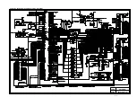
Страница 133: ...Appendix 2 Main PCB Circuit Diagram 1 3 CODE UK3227000 B48K272CIR 1 3 NAME ...
Страница 134: ...Appendix 3 Main PCB Circuit Diagram 2 3 CODE UK3227000 B48K272CIR 2 3 NAME ...
Страница 135: ...CODE UK3227000 B48K272CIR 3 3 NAME Appendix 4 Main PCB Circuit Diagram 3 3 ...


