USER’S GUIDE
CHAPTER 2 –8
MANUAL FEED SLOT
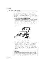
The multi-purpose sheet feeder also has a manual feed slot. You can
manually load paper sheet by sheet from this slot. You do not need to
remove paper from the multi-purpose sheet feeder when using the manual
feed slot.
❏
When you load one sheet of paper manually:
You do not need to choose manual feed in the Setup dialog box of your
printer driver. Holding the selected size of paper in the selected
orientation (Portrait or Landscape), place the side of the paper you wish
to print on face down into the manual feed slot. Align the paper at the
center of the manual feed slot, and be sure to insert it all the way. (
➀
)
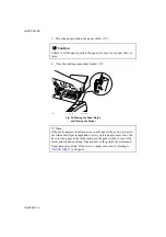
Move the paper guide of the manual feed slot to the paper width you are
using. (
➁
)
Fig. 2-7 Moving the Paper Guide
❏
When you load more than one sheet of paper manually:
Open the Setup dialog box of the supplied Windows printer driver and
choose Manual Feed in the Paper Source section. Follow the above
instructions to load the first page. The printer automatically starts
printing. After the first page is printed, the dialog box appears and
prompts you to load the next page. Load a sheet and choose OK to
resume printing. Repeat these steps until you have finished printing all
the pages.
!
Caution
If bi-directional communication is not operational between the printer and
the computer, such as when the printer is shared on a network, the dialog
box will not appear to load the next page. Manual paper feeding is not
recommended when your printer is attached to a network.
Содержание HL-720
Страница 1: ...SERVICE MANUAL MODEL HL 720 730 730Plus R LASER PRINTER ...
Страница 36: ...II 19 1 3 10 Engine I O HL 720 Fig 2 21 shows the engine interface circuit Fig 2 21 ...
Страница 37: ...II 20 HL 730 730Plus Fig 2 22 shows the engine interface circuit Fig 2 22 ...
Страница 61: ... Fig 3 18 2 4 1 1 1 ...
Страница 92: ...SERVICE MANUAL MODEL HL 760 R LASER PRINTER ...
Страница 109: ...II 8 1 3 4 DRAM Two 4M bit DRAMs x 16bits are used as the RAM Fig 2 6 ...
Страница 113: ...II 12 1 3 10 Engine I O Fig 2 12 shows the engine interface circuit Fig 2 12 ...
Страница 114: ...II 13 1 3 11 Paper Feed Motor Drive Circuit Fig 2 13 ...
Страница 133: ...Appendix 2 Main PCB Circuit Diagram 1 3 CODE UK3227000 B48K272CIR 1 3 NAME ...
Страница 134: ...Appendix 3 Main PCB Circuit Diagram 2 3 CODE UK3227000 B48K272CIR 2 3 NAME ...
Страница 135: ...CODE UK3227000 B48K272CIR 3 3 NAME Appendix 4 Main PCB Circuit Diagram 3 3 ...


