


M-2
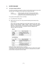
No DC power
li d
Possible cause
Step
Check
Result
Remedy
AC power
supply
1
Is AC power supplied between
connectors CN1-L and CN1-N
when the power plug is plugged into
the outlet?
No
Follow the same
check procedure of M-
1 “No AC power
supplied”.
Wiring, DC load
2
Turn the power switch OFF and
disconnect the P4 connector (panel
sensor PCB).
Measure the voltages between the
terminals.
Do the measured voltage satisfy the
prescribed value in the table below?
Yes
Turn the power switch
OFF, connect the
connector
disconnected, and turn
the power switch ON
again.
If the protector circuit
is activated, check the
connector, the wiring
from the connector,
and the DC load.
Power supply
input unit
3
No
Replace the power
supply input unit after
unplugging the
power cord from the
power outlet.
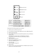
M-3
Main motor unrotated
Possible cause
Step
Check
Result
Remedy
Connection
failure of
connector
1
Is the connection of connector P5
on the panel sensor PCB correct?
No
Reconnect the
connector.
Main motor
(M1)
2
Disconnect connector P5 from the
panel sensor PCB.
Measure the resistance between
the connector pins of the main
motor by using a circuit tester.
No
Replace the Main
motor.
Panel sensor
circuit
Do the measured resistance satisfy
the prescribed value in the table
below?
Yes
Replace the panel
sensor PCB.
Replace the Main
PCB.
Содержание HL-720
Страница 1: ...SERVICE MANUAL MODEL HL 720 730 730Plus R LASER PRINTER ...
Страница 36: ...II 19 1 3 10 Engine I O HL 720 Fig 2 21 shows the engine interface circuit Fig 2 21 ...
Страница 37: ...II 20 HL 730 730Plus Fig 2 22 shows the engine interface circuit Fig 2 22 ...
Страница 61: ... Fig 3 18 2 4 1 1 1 ...
Страница 92: ...SERVICE MANUAL MODEL HL 760 R LASER PRINTER ...
Страница 109: ...II 8 1 3 4 DRAM Two 4M bit DRAMs x 16bits are used as the RAM Fig 2 6 ...
Страница 113: ...II 12 1 3 10 Engine I O Fig 2 12 shows the engine interface circuit Fig 2 12 ...
Страница 114: ...II 13 1 3 11 Paper Feed Motor Drive Circuit Fig 2 13 ...
Страница 133: ...Appendix 2 Main PCB Circuit Diagram 1 3 CODE UK3227000 B48K272CIR 1 3 NAME ...
Страница 134: ...Appendix 3 Main PCB Circuit Diagram 2 3 CODE UK3227000 B48K272CIR 2 3 NAME ...
Страница 135: ...CODE UK3227000 B48K272CIR 3 3 NAME Appendix 4 Main PCB Circuit Diagram 3 3 ...


