


3.5
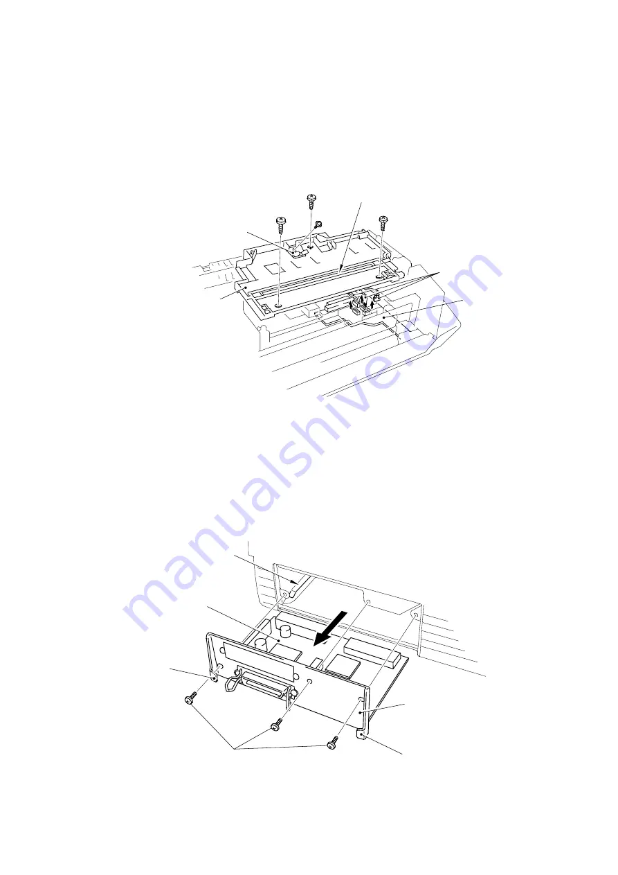
Scanner Unit
(1) Remove the three screws.
(2) Lift out the scanner unit.
(3) Disconnect the three connectors of the scanner unit from the panel sensor PCB.
(4) Remove the screw and disassemble the Toner sensor PCB from the Scanner unit.
Fig. 3.6
NOTE: Never touch the inside of the scanner unit or the mirror when disassembling or
reassembling. If there is any garbage or dust on the mirror, blow it off.
3.6
Main PCB Assy
(1) Remove three screws securing the main PCB holder on the back side of the printer.
(2) Grasp the hooks at left and right and draw out the main PCB assy.
Fig. 3.7
1/
.
#8 4
.
4
1/
1 1/
'132 1,2 1(*
4
Содержание HL-720
Страница 1: ...SERVICE MANUAL MODEL HL 720 730 730Plus R LASER PRINTER ...
Страница 36: ...II 19 1 3 10 Engine I O HL 720 Fig 2 21 shows the engine interface circuit Fig 2 21 ...
Страница 37: ...II 20 HL 730 730Plus Fig 2 22 shows the engine interface circuit Fig 2 22 ...
Страница 61: ... Fig 3 18 2 4 1 1 1 ...
Страница 92: ...SERVICE MANUAL MODEL HL 760 R LASER PRINTER ...
Страница 109: ...II 8 1 3 4 DRAM Two 4M bit DRAMs x 16bits are used as the RAM Fig 2 6 ...
Страница 113: ...II 12 1 3 10 Engine I O Fig 2 12 shows the engine interface circuit Fig 2 12 ...
Страница 114: ...II 13 1 3 11 Paper Feed Motor Drive Circuit Fig 2 13 ...
Страница 133: ...Appendix 2 Main PCB Circuit Diagram 1 3 CODE UK3227000 B48K272CIR 1 3 NAME ...
Страница 134: ...Appendix 3 Main PCB Circuit Diagram 2 3 CODE UK3227000 B48K272CIR 2 3 NAME ...
Страница 135: ...CODE UK3227000 B48K272CIR 3 3 NAME Appendix 4 Main PCB Circuit Diagram 3 3 ...


