


REGULATIONS
ix
For Finland and Sweden
LUOKAN 1 LASERLAITE
KLASS 1 LASER APPARAT
Varoitus! Laitteen käyttäminen muulla kuin tässä käyttöohjeessa mainitulla tavalla saattaa
altistaa käyttäjän turvallisuusluokan 1 ylittävälle näkymättömälle lasersäteilylle.
Varning – Om apparaten används på annat sätt än i denna Bruksanvisning specificerats, kan
användaren utsättas för osynlig laserstrålning, som överskrider gränsen för laserklass 1.
IMPORTANT - For Your Safety
To ensure safe operation the three-pin electrical plug supplied must be inserted only into a
standard three-pin power point which is properly grounded through normal household wiring.
Extension cords used with the equipment must be three-pin plug type and correctly wired to
provide proper grounding. Incorrectly wired extension cords may cause personal injury and
equipment damage.
The fact that the equipment operates satisfactorily does not imply that the power is grounded
and that the installation is completely safe. For your safety, if in any doubt about the effective
grounding of the power, consult a qualified electrician.
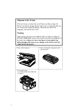
Disconnect device
This printer must be installed near a power outlet, which is easily accessible. In case of
emergencies, you must disconnect the power cord from the power outlet in order to shut off
power completely.
Geräuschemission / Acoustic Noise Emission (For Germany Only)
Lpa < 70 dB (A) DIN 45635-19-01-KL2
Содержание HL-720
Страница 1: ...SERVICE MANUAL MODEL HL 720 730 730Plus R LASER PRINTER ...
Страница 36: ...II 19 1 3 10 Engine I O HL 720 Fig 2 21 shows the engine interface circuit Fig 2 21 ...
Страница 37: ...II 20 HL 730 730Plus Fig 2 22 shows the engine interface circuit Fig 2 22 ...
Страница 61: ... Fig 3 18 2 4 1 1 1 ...
Страница 92: ...SERVICE MANUAL MODEL HL 760 R LASER PRINTER ...
Страница 109: ...II 8 1 3 4 DRAM Two 4M bit DRAMs x 16bits are used as the RAM Fig 2 6 ...
Страница 113: ...II 12 1 3 10 Engine I O Fig 2 12 shows the engine interface circuit Fig 2 12 ...
Страница 114: ...II 13 1 3 11 Paper Feed Motor Drive Circuit Fig 2 13 ...
Страница 133: ...Appendix 2 Main PCB Circuit Diagram 1 3 CODE UK3227000 B48K272CIR 1 3 NAME ...
Страница 134: ...Appendix 3 Main PCB Circuit Diagram 2 3 CODE UK3227000 B48K272CIR 2 3 NAME ...
Страница 135: ...CODE UK3227000 B48K272CIR 3 3 NAME Appendix 4 Main PCB Circuit Diagram 3 3 ...


