App. 1-18
Confidential
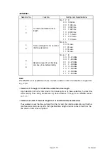
<WSW13>
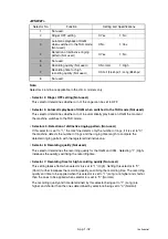
Note:
The modem should be adjusted according to the user's line conditions.
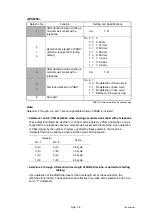
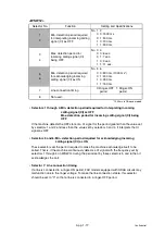
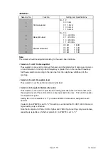
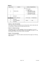
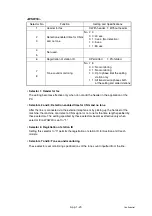
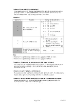
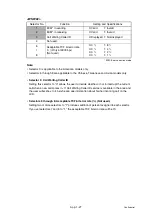
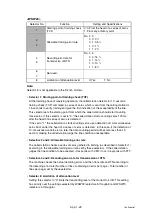
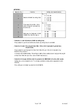
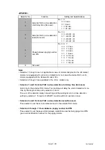
• Selectors 1 and 2: Cable equalizer
These selectors are used to improve the pass-band characteristics of analogue signals on
a line. Attenuation in the high-band frequency is greater than in the low-band frequency.
Set these selectors according to the distance from the telephone switchboard to the
machine.
• Selectors 3 and 4: Reception level
These selectors set the optimum receive signal level.
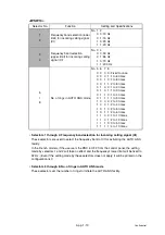
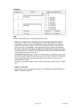
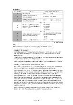
• Selectors 5 through 8: Modem attenuator
These selectors are used to adjust the transmitting level attenuation of the modem when
the reception level at the remote station is improper due to line loss. This function applies
for G3 protocol signals.
Setting two or more selectors to "1" produces addition of attenuation assigned to each
selector.
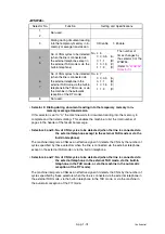
If selector 8 on WSW23 is set to "0," this setting is so limited that 10 dB (1 dB in France) or
higher setting only is effective.
Note that in Japan and China, 9 dB or higher and 2 dB or higher settings only are effective,
respectively, regardless of whether selector 8 on WSW23 is set to "0."
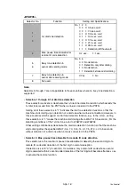
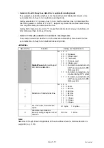
Selector No.
Function
Setting and Specifications
1
2
Cable equalizer
No. 1 2
0 0: 0 km
0 1: 1.8 km
1 0: 3.6 km
1 1: 5.6 km
3
4
Reception level
No. 3 4
0 0: -43 dBm
0 1: -47 dBm
1 0: -49 dBm
1 1: -51 dBm
5
I
8
Modem attenuator
0: 0 dB
1: 8 dB
0: 0 dB
1: 4 dB
0: 0 dB
1: 2 dB
0: 0 dB
1: 1 dB
Содержание DCP-7030
Страница 78: ...2 2 Confidential 2 PERIODICAL PEPLACEMENT PARTS There are no parts to be replaced periodically ...
Страница 133: ...3 55 Confidential 8 12 8 ADDRESS LABEL 1 Remove the Address label from the Panel unit Fig 3 53 Address label Panel unit ...
Страница 150: ...3 72 Confidential 8 27 FILTER ASSY 1 Remove the Filter ASSY from the Main body Fig 3 72 Filter ASSY Front side ...
Страница 178: ...3 100 Confidential 8 39 RUBBER FOOT 1 Remove the two Rubber feet from the Main body Fig 3 104 Rubber foot Front side ...
Страница 201: ...5 5 Confidential Print sample Fig 5 1 ...
Страница 226: ...5 30 Confidential Location of fans Fig 5 13 Fan motor 60 unit Right side ...
Страница 233: ...6 1 Confidential CHAPTER 6 CIRCUIT DIAGRAMS WIRING DIAGRAM High voltage Power Supply PCB Circuit Diagram ...
Страница 234: ...6 2 Confidential LVPS PCB Circuit Diagram 100V ...
Страница 235: ...6 3 Confidential LVPS PCB Circuit Diagram 200V ...
Страница 239: ...6 7 Confidential Wiring Diagram ...

