7. ADJUSTMENTS
SL-710A
67
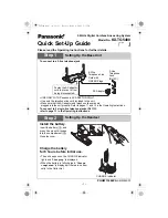
7-6. Adjusting the needle bar height
Reference line (a), which is the second line from the
bottom of the needle bar (1)(fourth line from the bottom
when using a DA X 1 needle) should be aligned with the
lower edge of the needle bar bush D (2) as shown in the
illustration when the needle bar (1) is at its lowest position.
1. Turn the machine pulley to set the needle bar (1) to its
lowest position.
2. Remove the oil cap (3).
3. Loosen the screw (4) and then move the needle bar
(1) up or down to adjust its position.
4. Securely tighten the screw (4).
5. Replace the oil cap (3).
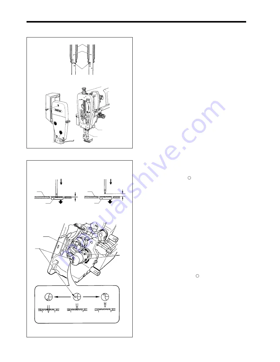
7-7. Adjusting the needle and feed mechanism timing
The standard position for point of the needle is as
described below when the feed dog (1) is lowered from its
highest position until it is aligned with the top of the needle
plate (2). (At this time, the “ ” mark (4) on the vertical cam
(3) should be aligned with the “-“ mark on the lower shaft.
Refer to [A] in the illustration.)
[For thin and medium-thick materials]
The top of the feed dog (1) and the top of the
needle plate (2) should be aligned, and the point of
the needle should be approximately 1 mm below
the needle plate (2).
[For thick materials]
The top of the feed dog (1) and the top of the
needle plate (2) should be aligned, and there
should be a clearance of approximately 3 mm
between the point of the needle and the needle
plate (2).
1. Tilt back the machine head. (Refer to page 8.)
2. Loosen the two set screws (5), and then turn the
vertical cam (3) sligtly to adjust the timing.
• If setting the timing to the standard timing, turn the
vertical cam (3) until the “ ” mark (4) is aligned with
the “-“ mark on the lower shaft ([A] in the illustration).
• To prevent material slippage from occurring, retard
the needle timing. (Turn the vertical cam (3) in the
direction of (B). Refer to [B] in the illustration.)
• To improve thread tightening, advance the direction
of (C). Refer to [C] in the illustration.)
Note
:
Do not turn the vertical cam (3) too far in the
direction of (C), otherwise it could cause the
needle to break.
3. After adjustment is completed, securely tighten the
two screws (5).
0924M
1197M
DB X 1 DA X 1
DP X 5
(2)
(1)
(4)
(3)
(1)
(a)
0926M
<For thin and medium-thick materials>
Approx. 3 mm
(1)
(2)
(2)
(1)
<For thick materials>
Approx. 1 mm
(3)
(4)
(5)
[C]
[A]
[B]
Needle timinig is
Advanced
(Standard)
Needle timinig is
retarded
0927M
(C)
(B)
Содержание DB2-DD7100
Страница 9: ...1 SPECIFICATIONS SL 710A 2 Operation panel Operation panel Part code B 40 J80627 001 B 100 J80629 001 ...
Страница 112: ...21 WIRING DIAGRAMS SL 710A 105 21 WIRING DIAGRAMS 21 1 Control circuit board assembly 1 6 1889M ...
Страница 113: ...21 WIRING DIAGRAMS SL 710A 106 Control circuit board assembly 2 6 1934M ...
Страница 114: ...21 WIRING DIAGRAMS SL 710A 107 Control circuit board assembly 3 6 1890M ...
Страница 115: ...21 WIRING DIAGRAMS SL 710A 108 Control circuit board assembly 4 6 1891M ...
Страница 116: ...21 WIRING DIAGRAMS SL 710A 109 Control circuit board assembly 5 6 1892M ...
Страница 117: ...21 WIRING DIAGRAMS SL 710A 110 Control circuit board assembly 6 6 1893M ...
Страница 119: ...21 WIRING DIAGRAMS SL 710A 112 Power supply circuit board assembly DD7100A 710A D ADD1 110V 2 3 1895M ...
Страница 120: ...21 WIRING DIAGRAMS SL 710A 113 Power supply circuit board assembly DD7100A 710A D ADD1 110V 3 3 1896M ...
Страница 121: ...21 WIRING DIAGRAMS SL 710A 114 Power supply circuit board assembly DD7100A 710A D ADD1 240V 1 3 1897M ...
Страница 122: ...21 WIRING DIAGRAMS SL 710A 115 Power supply circuit board assembly DD7100A 710A D ADD1 240V 2 3 1898M ...
Страница 123: ...21 WIRING DIAGRAMS SL 710A 116 Power supply circuit board assembly DD7100A 710A D ADD1 240V 3 3 1899M ...
Страница 124: ...21 WIRING DIAGRAMS SL 710A 117 Power supply circuit board assembly DD7100A 710A D ADD3 220V 1 3 1900M ...
Страница 125: ...21 WIRING DIAGRAMS SL 710A 118 Power supply circuit board assembly DD7100A 710A D ADD3 220V 2 3 1901M ...
Страница 126: ...21 WIRING DIAGRAMS SL 710A 119 Power supply circuit board assembly DD7100A 710A D ADD3 220V 3 3 1902M ...
Страница 128: ...21 WIRING DIAGRAMS SL 710A 121 Power supply circuit board assembly DD7100 D NDD1 120V 2 3 1904M ...
Страница 129: ...21 WIRING DIAGRAMS SL 710A 122 Power supply circuit board assembly DD7100 D NDD1 120V 3 3 1905M ...
Страница 130: ...21 WIRING DIAGRAMS SL 710A 123 Power supply circuit board assembly DD7100 D NDD1 230V 1 3 1906M ...
Страница 131: ...21 WIRING DIAGRAMS SL 710A 124 Power supply circuit board assembly DD7100 D NDD1 230V 2 3 1907M ...
Страница 132: ...21 WIRING DIAGRAMS SL 710A 125 Power supply circuit board assembly DD7100 D NDD1 230V 3 3 1908M ...
Страница 133: ...21 WIRING DIAGRAMS SL 710A 126 Power supply circuit board assembly DD7100 D NDD3 240V 1 3 1909M ...
Страница 134: ...21 WIRING DIAGRAMS SL 710A 127 Power supply circuit board assembly DD7100 D NDD3 240V 2 3 1910M ...
Страница 135: ...21 WIRING DIAGRAMS SL 710A 128 Power supply circuit board assembly DD7100 D NDD3 240V 3 3 1911M ...
Страница 136: ...21 WIRING DIAGRAMS SL 710A 129 21 4 Transformer 1912M ...
Страница 137: ...21 WIRING DIAGRAMS SL 710A 130 21 5 Operation panel B 40 Operation panel B 40 1 3 1913M ...
Страница 138: ...21 WIRING DIAGRAMS SL 710A 131 Operation panel B 40 2 3 1914M ...
Страница 139: ...21 WIRING DIAGRAMS SL 710A 132 Operation panel B 40 3 3 1915M ...
Страница 140: ...21 WIRING DIAGRAMS SL 710A 133 21 6 Operation panel B 100 Operation panel B 100 1 3 1916M ...
Страница 141: ...21 WIRING DIAGRAMS SL 710A 134 Operation panel B 100 2 3 1917M ...
Страница 142: ...21 WIRING DIAGRAMS SL 710A 135 Operation panel B 100 3 3 1918M ...