6. ASSEMBLY
SL-710A
57
6-27. Safety switch
1. Tilt back the machine head.
2. Install the safety switch (1) to the bed with the washer
(2) and screw (3).
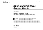
6-28. Arm cover, rear cover and bobbin winder tension assembly
1. Install the arm cover (1) to the arm with the four
screws (2).
2. Install the rear cover (3) to the arm with the seven
screws (4).
3. Insert the bobbin wider tension (5) into the mounting
hole so that it faces as shown in the illustration, and
then secure it with the set screw (6).
6-29. Other devices
Refer to the Instruction Manual for details on installing other devices.
1803M
(6)
(3)
(2)
(4)
(5)
(1)
1802M
(3)
(1)
(2)
Содержание DB2-DD7100
Страница 9: ...1 SPECIFICATIONS SL 710A 2 Operation panel Operation panel Part code B 40 J80627 001 B 100 J80629 001 ...
Страница 112: ...21 WIRING DIAGRAMS SL 710A 105 21 WIRING DIAGRAMS 21 1 Control circuit board assembly 1 6 1889M ...
Страница 113: ...21 WIRING DIAGRAMS SL 710A 106 Control circuit board assembly 2 6 1934M ...
Страница 114: ...21 WIRING DIAGRAMS SL 710A 107 Control circuit board assembly 3 6 1890M ...
Страница 115: ...21 WIRING DIAGRAMS SL 710A 108 Control circuit board assembly 4 6 1891M ...
Страница 116: ...21 WIRING DIAGRAMS SL 710A 109 Control circuit board assembly 5 6 1892M ...
Страница 117: ...21 WIRING DIAGRAMS SL 710A 110 Control circuit board assembly 6 6 1893M ...
Страница 119: ...21 WIRING DIAGRAMS SL 710A 112 Power supply circuit board assembly DD7100A 710A D ADD1 110V 2 3 1895M ...
Страница 120: ...21 WIRING DIAGRAMS SL 710A 113 Power supply circuit board assembly DD7100A 710A D ADD1 110V 3 3 1896M ...
Страница 121: ...21 WIRING DIAGRAMS SL 710A 114 Power supply circuit board assembly DD7100A 710A D ADD1 240V 1 3 1897M ...
Страница 122: ...21 WIRING DIAGRAMS SL 710A 115 Power supply circuit board assembly DD7100A 710A D ADD1 240V 2 3 1898M ...
Страница 123: ...21 WIRING DIAGRAMS SL 710A 116 Power supply circuit board assembly DD7100A 710A D ADD1 240V 3 3 1899M ...
Страница 124: ...21 WIRING DIAGRAMS SL 710A 117 Power supply circuit board assembly DD7100A 710A D ADD3 220V 1 3 1900M ...
Страница 125: ...21 WIRING DIAGRAMS SL 710A 118 Power supply circuit board assembly DD7100A 710A D ADD3 220V 2 3 1901M ...
Страница 126: ...21 WIRING DIAGRAMS SL 710A 119 Power supply circuit board assembly DD7100A 710A D ADD3 220V 3 3 1902M ...
Страница 128: ...21 WIRING DIAGRAMS SL 710A 121 Power supply circuit board assembly DD7100 D NDD1 120V 2 3 1904M ...
Страница 129: ...21 WIRING DIAGRAMS SL 710A 122 Power supply circuit board assembly DD7100 D NDD1 120V 3 3 1905M ...
Страница 130: ...21 WIRING DIAGRAMS SL 710A 123 Power supply circuit board assembly DD7100 D NDD1 230V 1 3 1906M ...
Страница 131: ...21 WIRING DIAGRAMS SL 710A 124 Power supply circuit board assembly DD7100 D NDD1 230V 2 3 1907M ...
Страница 132: ...21 WIRING DIAGRAMS SL 710A 125 Power supply circuit board assembly DD7100 D NDD1 230V 3 3 1908M ...
Страница 133: ...21 WIRING DIAGRAMS SL 710A 126 Power supply circuit board assembly DD7100 D NDD3 240V 1 3 1909M ...
Страница 134: ...21 WIRING DIAGRAMS SL 710A 127 Power supply circuit board assembly DD7100 D NDD3 240V 2 3 1910M ...
Страница 135: ...21 WIRING DIAGRAMS SL 710A 128 Power supply circuit board assembly DD7100 D NDD3 240V 3 3 1911M ...
Страница 136: ...21 WIRING DIAGRAMS SL 710A 129 21 4 Transformer 1912M ...
Страница 137: ...21 WIRING DIAGRAMS SL 710A 130 21 5 Operation panel B 40 Operation panel B 40 1 3 1913M ...
Страница 138: ...21 WIRING DIAGRAMS SL 710A 131 Operation panel B 40 2 3 1914M ...
Страница 139: ...21 WIRING DIAGRAMS SL 710A 132 Operation panel B 40 3 3 1915M ...
Страница 140: ...21 WIRING DIAGRAMS SL 710A 133 21 6 Operation panel B 100 Operation panel B 100 1 3 1916M ...
Страница 141: ...21 WIRING DIAGRAMS SL 710A 134 Operation panel B 100 2 3 1917M ...
Страница 142: ...21 WIRING DIAGRAMS SL 710A 135 Operation panel B 100 3 3 1918M ...