6. ASSEMBLY
SL-710A
55
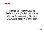
6-23. Tension release wire
1. With the holder (2) installed to the tension release wire
(1), pass the tension release wire (1) around the wire
holder (3) and install it to the solenoid lever (5) with the
two nuts (4).
* Tighten the two nuts (4) when the solenoid lever (5)
is at the center of the threaded part at the end of the
tension release wire (1).
2. Move the outside of the tension release wire (1) to the
position where the tension discs (7) start to open when
the solenoid plunger (6) is pressed by 2 - 3 mm, and
then tighten the set screw (8) to secure it in that
position.
* At this time, the holder (2) should be under the set
screw (8).
6-24. Ground wire
1. Secure the ground wire (1) to the bed with the screw
(2).
(The ground symbol (3) indicates the location.)
2. Group the ground wire (1), oil tube (4) [DD7100 only]
and thread trimmer solenoid cord (5) together in that
order, and secure them together with the cord holder
(6).
6-25. Operation panel
1. Pass the cord (2) of the operation panel (1) through
the hole in the arm.
2. Insert the two panel support brackets (3) into the
mounting holes.
3. Install the operation panel (1) to the arm, and then
secure it by tightening the two set screws (4).
1798M
(4)
(1)
(3)
(2)
1795M
1796M
2 - 3 mm
(7)
(4)
(2)
(6)
(1)
(8)
(3)
(5)
1797M
(3)
(4) DD7100 only
(2)
(1)
(6)
(5)
Содержание DB2-DD7100
Страница 9: ...1 SPECIFICATIONS SL 710A 2 Operation panel Operation panel Part code B 40 J80627 001 B 100 J80629 001 ...
Страница 112: ...21 WIRING DIAGRAMS SL 710A 105 21 WIRING DIAGRAMS 21 1 Control circuit board assembly 1 6 1889M ...
Страница 113: ...21 WIRING DIAGRAMS SL 710A 106 Control circuit board assembly 2 6 1934M ...
Страница 114: ...21 WIRING DIAGRAMS SL 710A 107 Control circuit board assembly 3 6 1890M ...
Страница 115: ...21 WIRING DIAGRAMS SL 710A 108 Control circuit board assembly 4 6 1891M ...
Страница 116: ...21 WIRING DIAGRAMS SL 710A 109 Control circuit board assembly 5 6 1892M ...
Страница 117: ...21 WIRING DIAGRAMS SL 710A 110 Control circuit board assembly 6 6 1893M ...
Страница 119: ...21 WIRING DIAGRAMS SL 710A 112 Power supply circuit board assembly DD7100A 710A D ADD1 110V 2 3 1895M ...
Страница 120: ...21 WIRING DIAGRAMS SL 710A 113 Power supply circuit board assembly DD7100A 710A D ADD1 110V 3 3 1896M ...
Страница 121: ...21 WIRING DIAGRAMS SL 710A 114 Power supply circuit board assembly DD7100A 710A D ADD1 240V 1 3 1897M ...
Страница 122: ...21 WIRING DIAGRAMS SL 710A 115 Power supply circuit board assembly DD7100A 710A D ADD1 240V 2 3 1898M ...
Страница 123: ...21 WIRING DIAGRAMS SL 710A 116 Power supply circuit board assembly DD7100A 710A D ADD1 240V 3 3 1899M ...
Страница 124: ...21 WIRING DIAGRAMS SL 710A 117 Power supply circuit board assembly DD7100A 710A D ADD3 220V 1 3 1900M ...
Страница 125: ...21 WIRING DIAGRAMS SL 710A 118 Power supply circuit board assembly DD7100A 710A D ADD3 220V 2 3 1901M ...
Страница 126: ...21 WIRING DIAGRAMS SL 710A 119 Power supply circuit board assembly DD7100A 710A D ADD3 220V 3 3 1902M ...
Страница 128: ...21 WIRING DIAGRAMS SL 710A 121 Power supply circuit board assembly DD7100 D NDD1 120V 2 3 1904M ...
Страница 129: ...21 WIRING DIAGRAMS SL 710A 122 Power supply circuit board assembly DD7100 D NDD1 120V 3 3 1905M ...
Страница 130: ...21 WIRING DIAGRAMS SL 710A 123 Power supply circuit board assembly DD7100 D NDD1 230V 1 3 1906M ...
Страница 131: ...21 WIRING DIAGRAMS SL 710A 124 Power supply circuit board assembly DD7100 D NDD1 230V 2 3 1907M ...
Страница 132: ...21 WIRING DIAGRAMS SL 710A 125 Power supply circuit board assembly DD7100 D NDD1 230V 3 3 1908M ...
Страница 133: ...21 WIRING DIAGRAMS SL 710A 126 Power supply circuit board assembly DD7100 D NDD3 240V 1 3 1909M ...
Страница 134: ...21 WIRING DIAGRAMS SL 710A 127 Power supply circuit board assembly DD7100 D NDD3 240V 2 3 1910M ...
Страница 135: ...21 WIRING DIAGRAMS SL 710A 128 Power supply circuit board assembly DD7100 D NDD3 240V 3 3 1911M ...
Страница 136: ...21 WIRING DIAGRAMS SL 710A 129 21 4 Transformer 1912M ...
Страница 137: ...21 WIRING DIAGRAMS SL 710A 130 21 5 Operation panel B 40 Operation panel B 40 1 3 1913M ...
Страница 138: ...21 WIRING DIAGRAMS SL 710A 131 Operation panel B 40 2 3 1914M ...
Страница 139: ...21 WIRING DIAGRAMS SL 710A 132 Operation panel B 40 3 3 1915M ...
Страница 140: ...21 WIRING DIAGRAMS SL 710A 133 21 6 Operation panel B 100 Operation panel B 100 1 3 1916M ...
Страница 141: ...21 WIRING DIAGRAMS SL 710A 134 Operation panel B 100 2 3 1917M ...
Страница 142: ...21 WIRING DIAGRAMS SL 710A 135 Operation panel B 100 3 3 1918M ...