6. ASSEMBLY
SL-710A
58
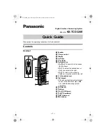
6-30. Connectors
1. Insert the pins for the solenoid cords and the safety
switch cord into the sewing machine 14P connector
(1).
• Match the numbers on the sewing machine 14P
connector (1) with the numbers (tube marks) (2) on
each pin.
• Insert the split ends (A) of each pin so that they face
toward the locking mechanism (B) for the sewing
machine 14P connector (1).
14P
Code
14P
Code
1
(Ground wire)
8
-
2
-
9
-
3
Thread trimmer solenoid
10
Thread trimmer solenoid
4
Thread wiper
11
Thread wiper
5
Quick reverse solenoid
12
Quick reverse solenoid
6
Reverse actuator
13
Reverse actuator
7
Safety switch
14
Safety switch
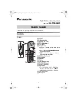
2. Insert the sewing machine 14P connector (1), the
lower thread detector mechanism 8P connector (3),
the solenoid-type presser lifter connector (4), the
synchronizer connector (5) and the operation panel
connector (6) into the control box circuit board.
3. Insert the motor connector (7) into the side of the
control box.
4. Bind the cords together with a cable tie (8).
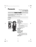
5. Tilt back the machine head.
6. Close the control box cover (9).
* Be careful not to clamp the cords inside the control
box.
7. Bind the cords with a cable tie (10).
1806M
(10)
(B)
(2)
(A)
(1)
(5)
(3)
(1)
(8)
(7)
(4)
(9)
(6)
1804M
1805M
Содержание DB2-DD7100
Страница 9: ...1 SPECIFICATIONS SL 710A 2 Operation panel Operation panel Part code B 40 J80627 001 B 100 J80629 001 ...
Страница 112: ...21 WIRING DIAGRAMS SL 710A 105 21 WIRING DIAGRAMS 21 1 Control circuit board assembly 1 6 1889M ...
Страница 113: ...21 WIRING DIAGRAMS SL 710A 106 Control circuit board assembly 2 6 1934M ...
Страница 114: ...21 WIRING DIAGRAMS SL 710A 107 Control circuit board assembly 3 6 1890M ...
Страница 115: ...21 WIRING DIAGRAMS SL 710A 108 Control circuit board assembly 4 6 1891M ...
Страница 116: ...21 WIRING DIAGRAMS SL 710A 109 Control circuit board assembly 5 6 1892M ...
Страница 117: ...21 WIRING DIAGRAMS SL 710A 110 Control circuit board assembly 6 6 1893M ...
Страница 119: ...21 WIRING DIAGRAMS SL 710A 112 Power supply circuit board assembly DD7100A 710A D ADD1 110V 2 3 1895M ...
Страница 120: ...21 WIRING DIAGRAMS SL 710A 113 Power supply circuit board assembly DD7100A 710A D ADD1 110V 3 3 1896M ...
Страница 121: ...21 WIRING DIAGRAMS SL 710A 114 Power supply circuit board assembly DD7100A 710A D ADD1 240V 1 3 1897M ...
Страница 122: ...21 WIRING DIAGRAMS SL 710A 115 Power supply circuit board assembly DD7100A 710A D ADD1 240V 2 3 1898M ...
Страница 123: ...21 WIRING DIAGRAMS SL 710A 116 Power supply circuit board assembly DD7100A 710A D ADD1 240V 3 3 1899M ...
Страница 124: ...21 WIRING DIAGRAMS SL 710A 117 Power supply circuit board assembly DD7100A 710A D ADD3 220V 1 3 1900M ...
Страница 125: ...21 WIRING DIAGRAMS SL 710A 118 Power supply circuit board assembly DD7100A 710A D ADD3 220V 2 3 1901M ...
Страница 126: ...21 WIRING DIAGRAMS SL 710A 119 Power supply circuit board assembly DD7100A 710A D ADD3 220V 3 3 1902M ...
Страница 128: ...21 WIRING DIAGRAMS SL 710A 121 Power supply circuit board assembly DD7100 D NDD1 120V 2 3 1904M ...
Страница 129: ...21 WIRING DIAGRAMS SL 710A 122 Power supply circuit board assembly DD7100 D NDD1 120V 3 3 1905M ...
Страница 130: ...21 WIRING DIAGRAMS SL 710A 123 Power supply circuit board assembly DD7100 D NDD1 230V 1 3 1906M ...
Страница 131: ...21 WIRING DIAGRAMS SL 710A 124 Power supply circuit board assembly DD7100 D NDD1 230V 2 3 1907M ...
Страница 132: ...21 WIRING DIAGRAMS SL 710A 125 Power supply circuit board assembly DD7100 D NDD1 230V 3 3 1908M ...
Страница 133: ...21 WIRING DIAGRAMS SL 710A 126 Power supply circuit board assembly DD7100 D NDD3 240V 1 3 1909M ...
Страница 134: ...21 WIRING DIAGRAMS SL 710A 127 Power supply circuit board assembly DD7100 D NDD3 240V 2 3 1910M ...
Страница 135: ...21 WIRING DIAGRAMS SL 710A 128 Power supply circuit board assembly DD7100 D NDD3 240V 3 3 1911M ...
Страница 136: ...21 WIRING DIAGRAMS SL 710A 129 21 4 Transformer 1912M ...
Страница 137: ...21 WIRING DIAGRAMS SL 710A 130 21 5 Operation panel B 40 Operation panel B 40 1 3 1913M ...
Страница 138: ...21 WIRING DIAGRAMS SL 710A 131 Operation panel B 40 2 3 1914M ...
Страница 139: ...21 WIRING DIAGRAMS SL 710A 132 Operation panel B 40 3 3 1915M ...
Страница 140: ...21 WIRING DIAGRAMS SL 710A 133 21 6 Operation panel B 100 Operation panel B 100 1 3 1916M ...
Страница 141: ...21 WIRING DIAGRAMS SL 710A 134 Operation panel B 100 2 3 1917M ...
Страница 142: ...21 WIRING DIAGRAMS SL 710A 135 Operation panel B 100 3 3 1918M ...