


8. CONTROL SYSTEM
SL-710A
75
8. CONTROL SYSTEM
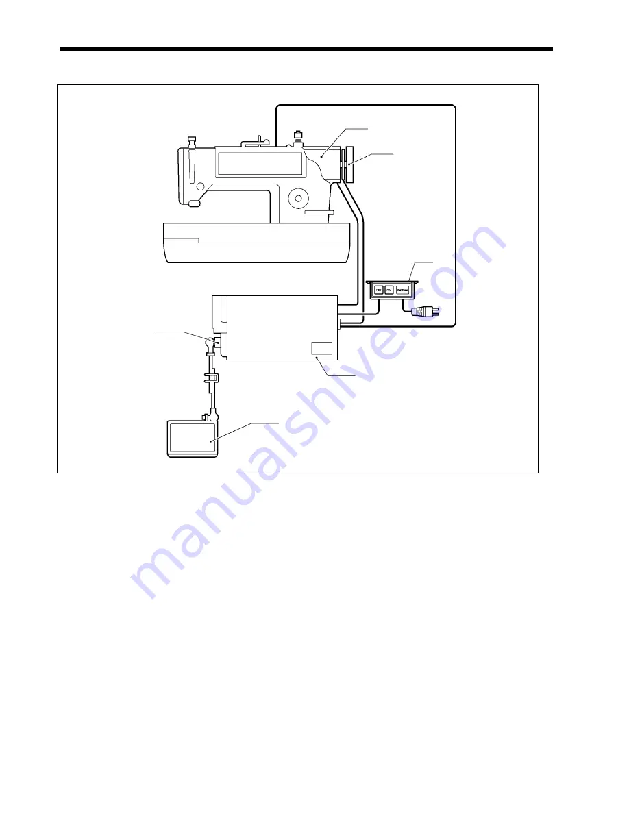
Turn on the power switch (1).
A. When the treadle is depressed
1. When the treadle (2) is depressed, a voltage corresponding to the amount of treadle depression is transmitted by the
treadle unit (3) to the control box (4).
2. The DD motor (5) that is directly linked to the sewing machine receives a voltage that corresponds to the treadle
depression amount from the control box (4), causing the DD motor (5) to operate at the speed represented by the
treadle depression amount, and this makes the sewing machine operate.
B. When the treadle is returned to the neutral position
1. When the treadle (2) is returned to the neutral position (when the operator's foot is removed from the treadle), a signal
indicating that the treadle is at the neutral position is transmitted by the treadle unit (3) to the control box (4), and the
electrical brake is then applied to slow the DD motor (5).
2. The encoder circuit board that is installed to the DD motor (5) sends a signal to the control box (4) so that the electrical
brake is applied in order to stop the sewing machine at the stopping position (needle up or needle down) set by the
pulley (6) that is attached to the DD motor (5).
C. When the treadle is depressed backward
1. When the treadle (2) is depressed backward, a signal indicating thread trimmer operation is transmitted by the treadle
unit (3) to the control box (4), and the DD motor (5) slows down to the thread trimming speed (inching speed).
2. The encoder circuit board that is installed to the DD motor (5) sends a signal to the control box (4) so that
the electrical brake is applied in order to stop the sewing machine at the needle up stopping position set by
the pulley (6) that is attached to the DD motor (5). The thread trimming operation is carried out
immediately before the sewing machine stops at the needle up stop position.
(5)
(6)
(4)
(1)
(3)
(2)
1825M
Содержание DB2-DD7100
Страница 9: ...1 SPECIFICATIONS SL 710A 2 Operation panel Operation panel Part code B 40 J80627 001 B 100 J80629 001 ...
Страница 112: ...21 WIRING DIAGRAMS SL 710A 105 21 WIRING DIAGRAMS 21 1 Control circuit board assembly 1 6 1889M ...
Страница 113: ...21 WIRING DIAGRAMS SL 710A 106 Control circuit board assembly 2 6 1934M ...
Страница 114: ...21 WIRING DIAGRAMS SL 710A 107 Control circuit board assembly 3 6 1890M ...
Страница 115: ...21 WIRING DIAGRAMS SL 710A 108 Control circuit board assembly 4 6 1891M ...
Страница 116: ...21 WIRING DIAGRAMS SL 710A 109 Control circuit board assembly 5 6 1892M ...
Страница 117: ...21 WIRING DIAGRAMS SL 710A 110 Control circuit board assembly 6 6 1893M ...
Страница 119: ...21 WIRING DIAGRAMS SL 710A 112 Power supply circuit board assembly DD7100A 710A D ADD1 110V 2 3 1895M ...
Страница 120: ...21 WIRING DIAGRAMS SL 710A 113 Power supply circuit board assembly DD7100A 710A D ADD1 110V 3 3 1896M ...
Страница 121: ...21 WIRING DIAGRAMS SL 710A 114 Power supply circuit board assembly DD7100A 710A D ADD1 240V 1 3 1897M ...
Страница 122: ...21 WIRING DIAGRAMS SL 710A 115 Power supply circuit board assembly DD7100A 710A D ADD1 240V 2 3 1898M ...
Страница 123: ...21 WIRING DIAGRAMS SL 710A 116 Power supply circuit board assembly DD7100A 710A D ADD1 240V 3 3 1899M ...
Страница 124: ...21 WIRING DIAGRAMS SL 710A 117 Power supply circuit board assembly DD7100A 710A D ADD3 220V 1 3 1900M ...
Страница 125: ...21 WIRING DIAGRAMS SL 710A 118 Power supply circuit board assembly DD7100A 710A D ADD3 220V 2 3 1901M ...
Страница 126: ...21 WIRING DIAGRAMS SL 710A 119 Power supply circuit board assembly DD7100A 710A D ADD3 220V 3 3 1902M ...
Страница 128: ...21 WIRING DIAGRAMS SL 710A 121 Power supply circuit board assembly DD7100 D NDD1 120V 2 3 1904M ...
Страница 129: ...21 WIRING DIAGRAMS SL 710A 122 Power supply circuit board assembly DD7100 D NDD1 120V 3 3 1905M ...
Страница 130: ...21 WIRING DIAGRAMS SL 710A 123 Power supply circuit board assembly DD7100 D NDD1 230V 1 3 1906M ...
Страница 131: ...21 WIRING DIAGRAMS SL 710A 124 Power supply circuit board assembly DD7100 D NDD1 230V 2 3 1907M ...
Страница 132: ...21 WIRING DIAGRAMS SL 710A 125 Power supply circuit board assembly DD7100 D NDD1 230V 3 3 1908M ...
Страница 133: ...21 WIRING DIAGRAMS SL 710A 126 Power supply circuit board assembly DD7100 D NDD3 240V 1 3 1909M ...
Страница 134: ...21 WIRING DIAGRAMS SL 710A 127 Power supply circuit board assembly DD7100 D NDD3 240V 2 3 1910M ...
Страница 135: ...21 WIRING DIAGRAMS SL 710A 128 Power supply circuit board assembly DD7100 D NDD3 240V 3 3 1911M ...
Страница 136: ...21 WIRING DIAGRAMS SL 710A 129 21 4 Transformer 1912M ...
Страница 137: ...21 WIRING DIAGRAMS SL 710A 130 21 5 Operation panel B 40 Operation panel B 40 1 3 1913M ...
Страница 138: ...21 WIRING DIAGRAMS SL 710A 131 Operation panel B 40 2 3 1914M ...
Страница 139: ...21 WIRING DIAGRAMS SL 710A 132 Operation panel B 40 3 3 1915M ...
Страница 140: ...21 WIRING DIAGRAMS SL 710A 133 21 6 Operation panel B 100 Operation panel B 100 1 3 1916M ...
Страница 141: ...21 WIRING DIAGRAMS SL 710A 134 Operation panel B 100 2 3 1917M ...
Страница 142: ...21 WIRING DIAGRAMS SL 710A 135 Operation panel B 100 3 3 1918M ...


