Bronkhorst®
Instruction Manual Controlled Evaporator and Mixer
9.17.126A
8
1.3
Product description
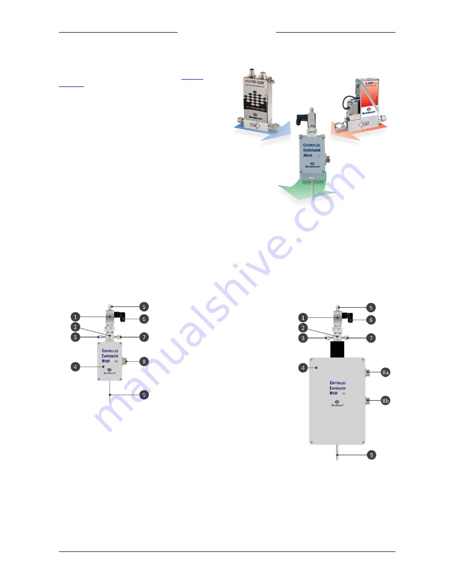
The CEM comprises a control valve (also called 'mixing valve'),
a mixing chamber and a heat exchanger (see
product
overview
), to add a liquid to a carrier gas and transform the
mix into a vapour.
A complete CEM system is a modular setup with the CEM
itself as the core component. To feed it with liquid and gas,
the CEM is complemented with a liquid flow meter with
control function (e.g. a mini CORI-FLOW or LIQUI-FLOW) and a
gas flow controller (e.g. an EL-FLOW Select). The liquid flow
meter uses the mixing valve of the CEM to control the liquid
flow rate.
The gas serves as a mixing component and as a means of
transport for the vapour, and is therefore also referred to as
'carrier gas'. The mixing valve atomizes the liquid and adds it
to the carrier gas, creating an aerosol, which is heated by the
CEM until it transforms into a vapour. To monitor the internal
temperature of the heat exchanger, the CEM incorporates a
PT100 temperature sensor. An internal safety switch prevents
overheating of the heat exchanger, by interrupting the control signal as soon as the temperature reaches 200 °C.
To control the liquid and gas supply flows and the CEM temperature, Bronkhorst offers an E-8000 readout and control unit.
This module contains a temperature controller for the heat exchanger and provides a user interface to operate the
instrumentation. The E-8000 module also serves as a power supply unit and can be optionally equipped with a fieldbus
interface for the CEM.
1.4
Product overview
W-10x / W-20x
W-30x
1. Control valve
2. Mixing chamber
3. Liquid inlet
4. Heat exchanger
5. Bleed connection
6. Control valve actuator connection
7. Gas inlet
8. Power and signal connection
a. Signal
b. Power
9. Vapour outlet


