Bronkhorst®
Instruction Manual Controlled Evaporator and Mixer
9.17.126A
12
Caution: when using the CEM without a Bronkhorst® readout and control unit (E-8000), observe the following guidelines:
·
The heat exchanger is not suitable for constant AC power supply
·
The heat exchanger should be incorporated in a temperature control circuit
·
The CEM does not contain a fuse. Consult the hook-up diagram for the recommended fuse type to be used for the
temperature control circuit
·
The safety switch inside the heat exchanger is not part of the AC power supply circuit
The recommended maximum cable length between the CEM and the control unit is 5 m. The internal electrical resistance
of the cable causes a deviation of the readout signal of the temperature sensor of the CEM (approximately 0.1 °C/m).
2.4
System assembly
2.4.1
Assembly tips
Tubing length
Because of the low flow rates fed to the CEM system, filling (and refreshing) the internal volume of the tubing can take a fair
amount of time. It will also take some time for the vapour flow to settle after flow setpoints are changed (response delay).
Fill time and response delay are affected mainly by the length and inside diameter of the tubing and the supported flow
ranges of the flow meters/controllers.
By minimizing tubing lengths between the flow meters/controllers and the CEM, the filling/response time can be kept as
short as possible. It can also reduce the impact of external disturbances like temperature, pressure and vibrations.
Tubing diameter and flexibility
·
Use tubing with a minimal diameter that still supports the required media flow; this will help keep the filling and
refreshing time of the fluidic lines as short as possible.
·
Preferably use hard tubing (as opposed to flexible), to prevent internal volume changes and reduce the impact of
ambient pressure fluctuations.
Insulation and heat tracing
Applying insulation material on the liquid and gas tubing can minimize the influence of ambient temperature gradients
on the supply side of the CEM. Alternatively, mount the entire system in a thermal enclosure to minimize temperature
influences from the environment.
Heat tracing
The ambient conditions or adding extra gases to the vapour after the CEM outlet can cause the vapour to condensate
before the process or further down the line. To prevent this, apply heat tracing tape or use heated tubing.
2.4.2
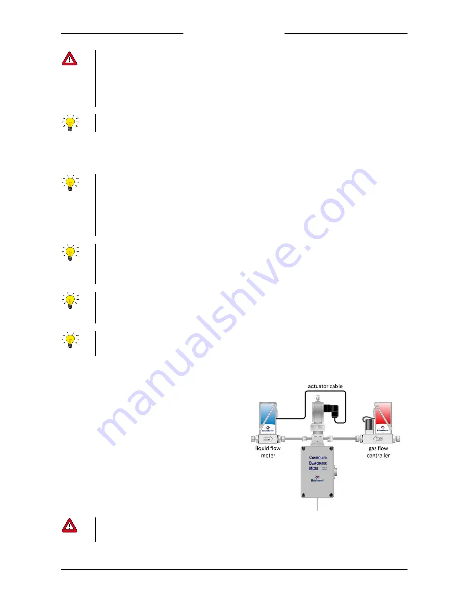
Basic assembly
·
Connect the outlet of the liquid flow meter to the liquid
inlet of the CEM (mind the FLOW arrow on the instrument
base)
·
Connect the outlet of the gas flow controller to the gas
inlet of the CEM (mind the FLOW arrow on the instrument
base)
·
Connect the vapour outlet directly to the
process/reactor/chamber
·
Connect an actuator cable from the liquid flow meter to
the mixing valve (refer to the hook-up diagrams of the
flow meter and the CEM to connect the required signals)
·
Check the fluidic system for leaks before applying full process pressure, especially if toxic, explosive or other dangerous
fluids are used
·
Do not apply pressure until all required electrical connections are made


