Brocade Communications Systems NetIron CER 2024C Скачать руководство пользователя страница 16

4

Brocade NetIron CES and Brocade NetIron CER Hardware Guide

53-0000080-03

Introduction

1

Brocade NetIron CER- RT 2048FX — accommodates 48-port 100/1000 Hybrid Fiber (HF) 
model with 2x10G XFP uplink ports. This device has the ability to simultaneously store up to 
1.5 million IPv4 routes and up to 256,000 IPv6 routes.
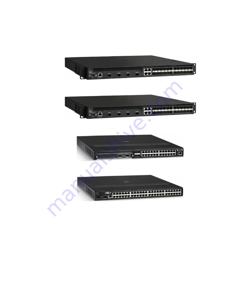
FIGURE 5

Brocade NetIron CER 2024C-4X-RT

FIGURE 6

Brocade NetIron CER 2024F-4X-RT

FIGURE 7

Brocade NetIron CER 2024C

FIGURE 8

Brocade NetIron CER 2048CX

Содержание NetIron CER 2024C

Страница 1: ...53 0000080 03 06 September 2013 Brocade NetIron CES and Brocade NetIron CER Devices Hardware Guide Supported Release Multi Service IronWare R05 5 00...

Страница 2: ...urce license agreements To find out which open source software is included in Brocade products view the licensing terms applicable to the open source software and obtain a copy of the programming sour...

Страница 3: ...ew Introduction 1 Product overview 5 Software features 5 Upgrade applications 6 Hardware features 6 Brocade NetIron CES 2024C 4X 7 Brocade NetIron CES 2024F 4X 7 Brocade NetIron CES 2024C 8 Brocade Ne...

Страница 4: ...9 Lifting precautions 29 Power precautions 30 Installation site preparation 32 Cabling infrastructure 32 Installation location 32 Redundant power supply installation 33 Installing an AC power supply 3...

Страница 5: ...net Module 69 Replacing the fan tray 69 Fiber optic module replacement 70 Removing a fiber optic module 70 Installing a new fiber optic module 71 Cabling a fiber optic module 72 Fiber optic connector...

Страница 6: ...vi Brocade NetIron CES and Brocade NetIron CER Hardware Guide 53 0000080 03 Port specifications 94 Console port pin assignments 94 Management port pin assignments 95 Power cords 96...

Страница 7: ...x Notice to the reader x Related publications x Getting technical help or reporting errors xi Audience This document is designed for system administrators with a working knowledge of Layer 2 and Layer...

Страница 8: ...Brocade NetIron XMR 4000 Brocade NetIron XMR 8000 Brocade NetIron XMR 16000 Brocade NetIron XMR 32000 Brocade MLX 4 Brocade MLX 8 Brocade MLX 16 Brocade MLX 32 Brocade MLXe 4 Brocade MLXe 8 Brocade M...

Страница 9: ...potential hazards NOTE A note provides a tip guidance or advice emphasizes important information or provides a reference to related information CAUTION A Caution statement alerts you to situations tha...

Страница 10: ...outing Configuration Guide Multi Service IronWare Traffic Management Configuration Guide Multi Service IronWare Multicast Configuration Guide Multi Service IronWare Multiprotocol Label Switch MPLS Con...

Страница 11: ...on CER Hardware Guide xi 53 0000080 03 In this chapter Getting technical help or reporting errors To contact Technical Support go to http www brocade com services support index page for the latest e m...

Страница 12: ...xii Brocade NetIron CES and Brocade NetIron CER Hardware Guide 53 0000080 03 In this chapter...

Страница 13: ...rse set of applications ranging from metro edge networks ISPs data centers large enterprises government networks and education or research can be addressed with the Brocade NetIron CES 2000 Series and...

Страница 14: ...RT accommodates 24 port 10 100 1000 RJ45 model with 4 combination 100 1000 Hybrid Fiber HF ports and 4x10G SFP uplinks This device has the ability to simultaneously store up to 1 5 million IPv4 routes...

Страница 15: ...ade NetIron CER 2048C accommodates 48 port 10 100 1000 Copper RJ45 model with 4 combination 100 1000 Hybrid Fiber HF ports Brocade NetIron CER RT 2048C accommodates 48 port 10 100 1000 Copper RJ45 mod...

Страница 16: ...48 port 100 1000 Hybrid Fiber HF model with 2x10G XFP uplink ports This device has the ability to simultaneously store up to 1 5 million IPv4 routes and up to 256 000 IPv6 routes FIGURE 5 Brocade Net...

Страница 17: ...e PBB functionalities in the same device With these capabilities the Brocade NetIron CER 2000 Series addresses a diverse set of needs in service provider networks and enterprise applications as well a...

Страница 18: ...e NetIron CER 2000 Series device with the premium software already installed For more information refer to the Multi Service IronWare Software Upgrade Guide Hardware features This section describes th...

Страница 19: ...ed FIGURE 11 Brocade NetIron CES 2024C 4X device Brocade NetIron CES 2024F 4X The Brocade NetIron CES 2024F 4X has twenty four 100 1000 MbE SFP ports plus four combination 10 100 1000 MbE RJ45 ports 4...

Страница 20: ...rocade NetIron CES 2024C device with the optional 2 ports of 10 G XFP uplink Brocade NetIron CES 2024F The Brocade NetIron CES 2024F has twenty four 100 1000 MbE SFP ports plus four combination 10 100...

Страница 21: ...dancy with one 500W AC power supply included FIGURE 15 Brocade NetIron CES 2048C device Brocade NetIron CES 2048CX Brocade NetIron CES 2048CX Copper has forty eight 10 100 1000 MbE RJ45 ports plus two...

Страница 22: ...ial management interface port labeled Console one 10 100 1000 MbE RJ45 out of band management port one resilient six unit fan tray and two AC power supply bays for 1 1 redundancy with one 500W AC powe...

Страница 23: ...e module slot for an optional field upgradable 2 port 10 GbE XFP module one DB9 serial management interface port labeled Console one 10 100 1000 MbE RJ45 out of band management port one resilient six...

Страница 24: ...for 1 1 redundancy with one 500W AC power supply included FIGURE 21 Brocade NetIron CER 2048C device Brocade NetIron CER 2048CX Brocade NetIron CER 2048CX Copper has forty eight 10 100 1000 MbE RJ45 p...

Страница 25: ...r supply included FIGURE 23 Brocade NetIron CER 2048F device Brocade NetIron CER 2048FX Brocade NetIron CER 2048FX Fiber router has forty eight 100 1000 MbE SFP ports plus two 10 GbE XFP ports one DB9...

Страница 26: ...r Pluggable SFP MSA compliant optical transceivers Serial Management Interface console port The Serial Management Interface enables you to configure and manage the device using a third party terminal...

Страница 27: ...twork the fiber connectors take precedence over the copper connectors These ports support true media automatic detection meaning the device selects the fiber or copper connector based on link availabi...

Страница 28: ...The SFP compliant fiber optic modules provide an optical transceiver or physical medium dependent PMD interface for fiber that can be used with the LAN physical layer PHY The following 100 Mbps and 1...

Страница 29: ...CER 2024 devices with 24 ports Ports 1 1 1 24 Port 2 1 optional 10 GbE uplink port E1MG 100BXU 100Base BXU SFP optic single mode fiber 1310nm LC connector This optic can only be connected to an E1MG...

Страница 30: ...Serial Unknown Port 1 2 Type Copper Vendor Unknown Version Unknown Part Unknown Serial Unknown Port 1 24 Type Copper Vendor Version Unknown Part Unknown Serial Unknown Port 2 1 Type 10GBASE SR SW XFP...

Страница 31: ...About redundant power supplies and power supply failure on page 19 AC power supplies Figure 25 shows a rear view of a device containing one AC power supply FIGURE 25 AC Power Supply DC power supplies...

Страница 32: ...or as a spare All other models support the NI CE 2000 FAN The fans in the devices include six four speed fans that operate at low speed medium speed medium high speed and high speed based on the ambie...

Страница 33: ...IP address and configure routing features To access the CONFIG mode you must already be logged into the Privileged level of the EXEC mode NOTE You can assign passwords using the Brocade Network Advis...

Страница 34: ...addresses Table 7 outlines the interfaces to which you can assign IP addresses In this table in band refers to an interface over which user packets are routed while out of band refers to an interface...

Страница 35: ...nagement module port For example to assign the IP address 10 0 1 1 to the management interface do the following 1 At the opening CLI prompt enter enable Brocade enable 2 Enter the following command at...

Страница 36: ...r enable Brocade enable 2 Enter the following command at the Privileged EXEC level prompt then press Enter This command erases the factory test configuration if still present Brocade erase startup con...

Страница 37: ...and manage the system only As a result this port has the same limited functionality as an IP host port You cannot enable and run routing protocols on the management port The management port supports s...

Страница 38: ...n CER Hardware Guide 53 0000080 03 Device connection 2 For information on cabling a fiber optic module see Cabling a fiber optic module on page 72 For information on cleaning a fiber optic module see...

Страница 39: ...s General requirements To manage the system you need the following items for serial connection to the router A management station such as a PC running a terminal emulation application A straight throu...

Страница 40: ...9 4 Once the device is physically installed plug the device into a nearby power source that adheres to the regulatory requirements outlined in this manual System power on page 43 5 Verify that the sys...

Страница 41: ...ld waste Contact your local waste disposal agency for the address of the nearest battery deposit site CAUTION All fiber optic interfaces use Class 1 lasers CAUTION Do not install the device in an envi...

Страница 42: ...with the rating limit for the circuit The maximum ampere ratings are usually printed on the devices near the input power connectors CAUTION Make sure you insert the power supply right side up It is po...

Страница 43: ...r removing the supply The device can be running while a power supply is being installed or removed but the power supply itself should not be connected to a power source Otherwise you could be injured...

Страница 44: ...nection to intra building or unexposed wiring or cabling only The intra building ports of the equipment or subassembly MUST NOT be metallically connected to interfaces that connect to the OSP or its w...

Страница 45: ...ce could void the user s authority to operate the equipment If you need to install a redundant power supply it may be easier to install it before mounting the device although the power supplies are ho...

Страница 46: ...er supply With the other hand support the underside of the power supply and insert the power supply into the empty power supply slot Press until the supply is completely in the slot so that the connec...

Страница 47: ...er wire has been cleaned and antioxidant is applied to the bare wire CAUTION To insure adequate bonding when attaching the provided Panduit LCD6 10AF two hole ground lug a minimum of 20 inch pounds of...

Страница 48: ...3 FIGURE 29 The DC power supply 4 Insert the wires into the DC wiring assembly Figure 30 5 Use the wire tightening screws to secure the wires 6 Insert the DC connector with wires to the power supply...

Страница 49: ...supply upside down although the supply will not engage with the power backplane when upside down The power supply is right side up when the manufacturer label is on the top 8 Secure the two screws ne...

Страница 50: ...e other end grounded to either a common bonding network or an isolated bonding network The connector must be crimped with the proper tool allowing it to be connected to both ground screws on the enclo...

Страница 51: ...device in a rack For rack mount installation Brocade recommends that you use the rack mount ears attached to the unit Each unit ships with rack ears attached to the front of the unit You can mount th...

Страница 52: ...n CES and Brocade NetIron CER Hardware Guide 53 0000080 03 Device installation 3 5 Inch offset rack mount position FIGURE 33 5 Inch offset rack mount position Mid rack mount position FIGURE 34 Mid rac...

Страница 53: ...Brocade NetIron CES and Brocade NetIron CER Hardware Guide 41 53 0000080 03 Device installation 3 Reverse rack mount position FIGURE 35 Reverse rack mount position...

Страница 54: ...in the rack as illustrated in Figure 36 2 Using a 2 hole grounding lug and a minimum 6 AWG grounding wire ground the chassis to either a common bonding network or an isolated bonding network 3 Procee...

Страница 55: ...ble for the outlet DANGER The intra building ports of the equipment or subassembly is suitable for connection to intra building or unexposed wiring or cabling only The intra building ports of the equi...

Страница 56: ...e cables are good and the connected device is powered on the link LEDs will light Observing the power status LEDs Table 9 lists the LEDs that show power status for the Brocade NetIron CES and Brocade...

Страница 57: ...s powered on and is operating normal Amber or green blinking The fan tray is not plugged in Amber The fan tray is plugged in but one or more fans are faulty PS1 labeled P1 Left side of front panel Off...

Страница 58: ...t be sure to discharge the voltage stored on the cable by touching the electrical contacts to ground surface Attaching a PC or terminal Follow the steps given below to attach a management station usin...

Страница 59: ...o your PC and to the system 2 Check the settings in your terminal emulation program In addition to the session settings listed above make sure the terminal emulation session is running on the same ser...

Страница 60: ...48 Brocade NetIron CES and Brocade NetIron CER Hardware Guide 53 0000080 03 PC or terminal attachment 3...

Страница 61: ...a PC or terminal attached to the device s serial Console port or 10BaseT 100BaseTX Ethernet management port or from a Telnet or SSH connection to the PC or terminal You can initiate a local Telnet SSH...

Страница 62: ...ng Scroll control By default the CLI uses a page mode to paginate displays that are longer than the number of rows in your terminal emulation window For example if you display a list of all the comman...

Страница 63: ...rs the output of the show interface command for port 3 1 so it displays only lines containing the word Internet This command can be used to display the IP address of the interface Brocade show interfa...

Страница 64: ...ow who command so it displays output starting with the first line that contains the word SSH This command can be used to display information about SSH connections to the Brocade device Syntax show com...

Страница 65: ...rent working directory chdir Change current working directory clear Clear table statistics keys clock Set clock configure Enter configuration mode copy Copy between flash tftp config code cp Copy file...

Страница 66: ...following regular expression matches output that contains the string abc followed by zero or more Xs abcX The plus sign matches on one or more sequential instances of a pattern For example the follow...

Страница 67: ...following regular expression matches output that contains 1 2 3 4 or 5 1 5 You can use the following expression symbols within the brackets These symbols are allowed only inside the brackets The caret...

Страница 68: ...56 Brocade NetIron CES and Brocade NetIron CER Hardware Guide 53 0000080 03 CLI Functionality 4...

Страница 69: ...ade NetIron CES 2024F Brocade NetIron CER 2024C Brocade NetIron CER 2024F models Power supply replacement You can replace a power supply while the Brocade device is powered on and running The power su...

Страница 70: ...u are not sure which supply has failed enter the following command at any CLI command prompt Brocade show chassis Brocade NetIron CES 2024C POWERS POWERS Power 1 3I50 AC 504W Installed OK Power 2 not...

Страница 71: ...g current AC power supply or direct current DC power supply All models have two power supply slots enabling you to install a second power supply for redundancy If desired you can install a second supp...

Страница 72: ...quired when removing an AC power supplies from a device 1 Unplug the power supply from the power source 2 Disconnect the power cord from the power supply 3 Unscrew the two power supply locking screws...

Страница 73: ...y on page 61 for details Installing the AC power supply Perform the following steps to install an AC power supply 1 Remove the power supply or cover plate currently in the power supply bay you wish to...

Страница 74: ...the two power supply locking screws located at the top left and bottom right hand corner of the power supply 5 Connect the power cord to the power supply Removing the DC power supply Required tools Y...

Страница 75: ...0 03 Power supply replacement 5 FIGURE 41 DC power supply screws 4 Unscrew the chassis attachment screws to unlock the power supply itself Figure 41 FIGURE 42 The DC wiring assembly 1 Chassis attachme...

Страница 76: ...n refer to the precautions in Power precautions on page 30 Use the following procedures for DC power supplies in Brocade devices Follow the steps given below to install an DC power supply 1 If necessa...

Страница 77: ...supply is completely in the slot so that the connectors on the back of the supply are fully engaged with the pins on the power backplane Figure 40 CAUTION Make sure you insert the power supply right s...

Страница 78: ...en connections to the power supply are made CAUTION For the NEBS compliant installation of Brocade devices with AC and DC system use a ground wire of at least 6 American Wire Gauge AWG The ground wire...

Страница 79: ...state To verify proper operation complete the following steps 1 Verify that the power supply s LED is steady green on the back of the device 2 Verify that the power supply was placed in power supply...

Страница 80: ...CX POWERS Power 1 3I50 AC 504W Installed OK Power 2 not present Total power budget for system 504 W FANS Metro fan tray fan 1 Status OK Speed LOW 50 Metro fan tray fan 2 Status OK Speed LOW 50 Metro f...

Страница 81: ...n the chassis 4 Use a 2 Phillips head screwdriver to fasten the screws on the 2 x10 Gigabit module Affix the screws loosely at first then tighten them once you are sure the board is properly positione...

Страница 82: ...wer up Fiber optic module replacement You can remove an SFP SFP or XFP from a port and replace it with a new one while the Brocade device is powered on and running This section provides information ab...

Страница 83: ...pulling the bail latch forward away from the front panel of the module This unlocks the module from the front panel NOTE The bail latch may be attached to either the top or the bottom of the mini GBIC...

Страница 84: ...e strongly recommends cleaning the cable connectors and the port connectors Refer to Fiber optic connector cleaning on page 73 3 Gently insert the cable connectors a tab on each connector should face...

Страница 85: ...1 1 tunable optic sfpp channel 5 show Channel 5 191 3THz 1567 13nm Syntax physical port port tunable optic sfpp channel channel number show Use the channel number parameter to specify the channel num...

Страница 86: ...74 Brocade NetIron CES and Brocade NetIron CER Hardware Guide 53 0000080 03 Fiber optic connector cleaning 5...

Страница 87: ...rference in which case the user will be required to correct the interference at his own expense CAUTION Changes or modifications made to this device which are not expressly approved by the party respo...

Страница 88: ...ed on the standard of the Voluntary Control Council For Interference by Information Technology Equipment VCCI If this equipment is used in a domestic environment radio disturbance may arise When such...

Страница 89: ...sting Communication Device for Office Use This device obtained EMC registration for office use Class A and may be used in places other than home Sellers and or users need to take note of this Taiwan E...

Страница 90: ...78 Brocade NetIron CES and Brocade NetIron CER Hardware Guide 53 0000080 03 China A China...

Страница 91: ...kann w hrend des Anschlie ens oder Annehmens des Netzteils laufen Nur das Netzteil sollte nicht an eine Stromquelle angeschlossen sein MISE EN GARDE Enlevez le cordon d alimentation d un bloc d alime...

Страница 92: ...tal with the rating limit for the circuit The maximum ampere ratings are usually printed on the devices near the input power connectors VORSICHT Stromkreise Verdrahtung und berlastschutz d rfen nicht...

Страница 93: ...ierda y la abertura del ventilador queda a la derecha CAUTION For the DC input circuit DC power supply part number RPS9 DC make sure there is a 20 amp circuit breaker minimum 48VDC double pole on the...

Страница 94: ...ca el comando write memory escribir memoria para guardar la configuraci n en ejecuci n en el archivo startup config CAUTION If you do not install a module in a slot you must keep the slot panel in pla...

Страница 95: ...ement uniquement Une zone acc s r glement est r serv e au personnel de maintenance qui peut y acc der uniquement l aide d un verrou d une cl ou d un outil sp cifique ou via d autres proc dures de s cu...

Страница 96: ...den Das 6 AWG Kabel muss mithilfe eines geeigneten Crimp Werkzeugs mit einem normgerechten Crimp Verbinder verbunden werden MISE EN GARDE Pour un syst me CC num ro de pi ce RPS9 DC utilisez un fil de...

Страница 97: ...s dispositifs progressivement de bas en haut du plus lourd au plus l ger PELIGRO Monte los instrumentos que instale en un bastidor o armario lo m s bajos posible Ponga el instrumento m s pesado en la...

Страница 98: ...ocade recommends that you disconnect the power supply from AC power before installing or removing the supply The device can be running while a power supply is being installed or removed but the power...

Страница 99: ...hrdeten Bauelementen mit einem 1 Megaohm Reihenwiderstand ausgestattet sein DANGER Pour des raisons de s curit la dragonne ESD doit contenir une r sistance de s rie 1 m ga ohm PELIGRO Por razones de...

Страница 100: ...88 Brocade NetIron CES and Brocade NetIron CER Hardware Guide 53 0000080 03 Danger B...

Страница 101: ...ions This section contains the power specifications for the Brocade devices Table 14 provides the minimum and maximum voltage and current ratings Table 15 provides the maximum power calculations TABLE...

Страница 102: ...461 Brocade NetIron CER 2024C with 2x10G uplink installed 205 700 Brocade NetIron CER 2024F 4X RT 219 747 Brocade NetIron CER 2024F 4X with 4x10G uplink installed 315 1076 Brocade NetIron CER 2024F 1...

Страница 103: ...C 1 RU 1 7 inches 4 4 cm 17 44 in 44 3 cm 17 25 in 43 9 cm 16 5 Brocade NetIron CES 2048CX 1 RU 1 7 inches 4 4 cm 17 44 in 44 3 cm 17 25 in 43 9 cm 17 5 Brocade NetIron CES 2048F 1 RU 1 7 inches 4 4 c...

Страница 104: ...NetIron CER 2024F with 2x10G uplink installed 1 RU 1 7 inches 4 4 cm 17 44 in 44 3 cm 17 64 in 44 8 cm 17 5 Brocade NetIron CER 2048C 1 RU 1 7 inches 4 4 cm 17 44 in 44 3 cm 17 3 in 43 9 cm 16 5 Broc...

Страница 105: ...60825 1 Safety of Laser Products Part 1 Equipment Classification Requirements and User s Guide EN 60825 2 Safety of Laser Products Part 2 Safety of Optical Fibre Communications Systems CE EN60950 1 20...

Страница 106: ...as intra building interfaces only Type 2 or Type 4 ports as described in GR 1089 CORE Issue 4 and require isolation from the exposed OSP cabling The addition of Primary Protectors is not sufficient pr...

Страница 107: ...results with some terminals FIGURE 48 Console port pin assignments showing cable connection options to a terminal or PC Management port pin assignments The management port is an RJ 45 UTP connector Ta...

Страница 108: ...ord types international Country Plug style NEMA 5 15P 125V only USA Canada Japan other locations CEE 7 7 Schuko Continental Europe BS 1363A various locations AS 3112 Australia New Zealand IEC 60309 16...

Страница 109: ...gal X Puerto Rico X Russia X Saudi Arabia X Scotland X Singapore X South Africa X Spain X Sweden X Switzerland X Taiwan X Turkey X United Arab Emirate X United Kingdom X United States X TABLE 20 Power...

Страница 110: ...ulate the total power consumption on the system to see whether NEMA 5 15P can support the power draw as per the country s legal requirements or contact Brocade technical support Venezuela X Yugoslavia...

Отзывы: