


e-mail:
voice:
360.854.9559
fax:
866.783.1742
6
ESS-1 Installation and Operation Manual
SETUP CONT’D
4 - Start the “Device Installer” software.
a - Click on “SEARCH”
b - When the ESS-1 is found, click on the listed device. If more than one ESS-
1 is found, refer to the MAC address label attached to the bottom of the ESS-
1 case and click on the desired ESS-1, which should be highlighted.
c - Click on the “ASSIGN IP” button, then follow the instructions for setting a
static IP address, along with the subnet and gateway, if applicable.
5 – After the ESS-1 has rebooted, click the “SEARCH” button, the configured
ESS-1 should be listed. NOTE: You may have to click the search button
more than once after the reboot.
6 - Connect the desired serial device to either the RS-232 (DTE) or RS-422 port.
These ports are OR’d and the receive ports shouldn’t be used simultaneously.
The TX and RX LED’s are provided for monitoring data activity. Please refer
to the pin-out information below.
RS-232, DB-9 (DTE) male pin-out:
RS-422 pin-out:
Pins 1, 4, 6 are tied together
Refer to the label near the plug-in
Pin 2 - Receive data
screw terminals.
Pin 3 - Transmit data
JPR1, termination for the TX port
Pin 5 – Ground
JPR2, termination for the RX port
Pin 7 - RTS (when configured)
The cover must be removed to
Pin 8 - CTS (when configured)
access both jumpers.
Pin 9 - No connection
Note:
The case of the DB-9 connector is tied to the circuit ground through a
.01uf cap. (This is used to avoid ground loops.)
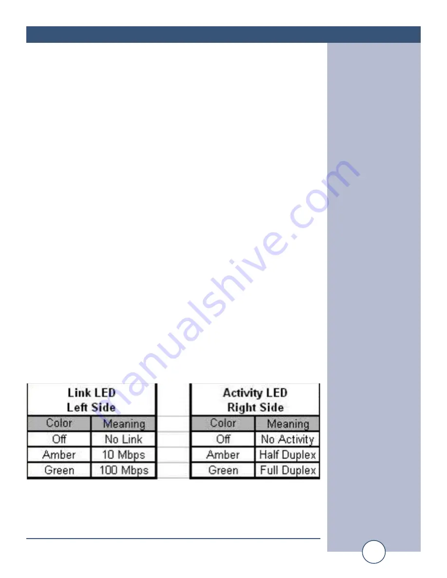
7 – Ethernet port LED indicator functions
8 - The ESS-1 is ready to use. The following Quick Start Examples may require
additional configurations.


