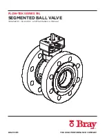
FLOW-TEK SERIES 19L SEGMENTED BALL VALVE
Installation, Operation, and Maintenance Manual
14 of 31
© 2021 BRAY INTERNATIONAL, INC. ALL RIGHTS RESERVED. BRAY.COM The Information
contained herein shall not be copied, transferred, conveyed, or displayed in any manner that would
violate its proprietary nature without the express written permission of Bray International, Inc.
8.0 INSTALLATION
8.1
Position
Bray’s segmented ball valve is designed to be mounted between
ASME or PN flanges. (Follow the direction of the
flow arrow plate
attached to body.)
WARNING
To avoid serious injury, keep hands, hair, clothing, etc. away from
the segment and seat when the valve is working.
CAUTION
If handle or actuator has been removed, do not rotate segment
beyond fully open or closed position, as this could cause damage
to sealing surfaces.
Provide proper overhead clearance to allow for disassembly
of the actuator from the valve body. (Refer to the appropriate
General Assembly Drawing
for proper clearances.)
Provide necessary support for accessories when center of gravity
for complete assembly is further off from pipe center line. (Refer
to the appropriate
General Assembly Drawing
for center of
gravity position.)
8.2
Cleaning
Before installing the valve, clean the pipeline of all contamination,
carbon deposits, welding chips, and other foreign material.
Carefully clean gasket surfaces to ensure a tight seal. Pipelines
must be correctly aligned to ensure that the valve is not fitted
under tension.
CAUTION
Before installation, check the order number, serial number,
and/or tag number to ensure that the valve and actuator being
installed are correct for the intended application.
Check the direction of fluid flow to ensure that the valve is
correctly installed. (Flow direction is indicated by the arrow on
the body.)
The
S19L
(metal seat with liner) shall not be installed in “end-of-
line” applications.


